2500_Users_Manual - 第384页
Trans lati on For mat s D-54 ProMaste r 2500 User Ma nual Figure D-24 A Close-up of the I ntel OMF286 Format Total Space Date Time Module Creator GDT Limit GDT Base IDT Limit IDT Base TSS Selector Data File Header 4 byte…
Translation Formats
ProMaster 2500 User Manual D-53
Intel OMF286 Format, Code 98
The Intel OMF286 format is a dynamically allocatable file format.
This format has three basic parts: the file header, data file module, and a
1-byte checksum. The file header is hexadecimal number (A2) that
identifies this file as an Intel OMF 286 format file. See Figure D-23.
The first 75 bytes of the data file module is the data file header. The
header information is generated and used by the development system
and is not used by the programmer, although some characters must fill
those bytes. The rest of the data file module consists of one partition.
The partition begins with a 20 byte table of contents. The table of contents
specifies the locations of ABSTXT (absolute text), DEBTXT (debug text),
the last location of this partition, and the location of the next partition.
The OMF286 format consists of only one partition so this field will be
zeros. The rest of the partition consists of sections. The actual data are
located in the sections. The first 3 bytes in each section specify the real
address of the text. The next 2 bytes state the length of the text, and the
remainder of the section is the text (or data). Following the final section of
the final partition is a 1-byte checksum representing the complement of
the sum of all the bytes in the file, including the header. The sum of the
checksum byte and the calculated checksum for the file should equal
zero. The programmer ignores this checksum.
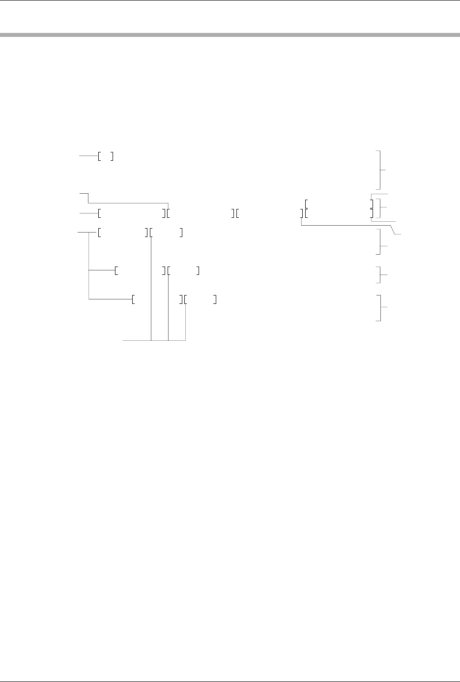
Figure D-23
A Sample of the Intel OMF286 Format
A2 F3 FF FF 00 30 38 2F-30 34 2F 38 37 30 38 3A
34 33 3A 30 31 1C 69 41-50 58 32 38 36 20 53 59
53 54 45 4D 20 42 55 49-4C 44 45 52 2C 20 56 33
2E 32 20 20 20 20 20 20-20 20 20 20 20 20 3F 01
00 80 FF 00 FF 00 40 81-FF 00 18 00
50 00 00 00
5B 66 00 00 6B EF 00 00-00 00 00 00 00 00 00 00
40 01 00 2C 00 00 00 00-04 28 00 00 00 00 00 00
00 00 00 6E 4F 00 02 00-00 00 00 00 00 00 00 00
04 00 04 00 00 00 00 28-00 20 00 28 00 28 00 00
00
70 01 00 2C 00 00 00-00 04 28 00 00 00 00 00
00 00 00 00 F5 38 00 02-00 00 00 00 00 00 00 00
00 00
A0 01 00 2C 00 00-00 00 04 28 00 00 00 00
00 00 00 00 00 33 39 00-02 00 00 00 00 00 00 00
00 00 04 00 04 00 00 00-00 28 00 20 00 28 00 28
00-00 00 00 04 28 00 00 00
-00 00 00 00 00 00 00 00
0431-2
Last Location
File Header
DEBTXT Location
ASBTXT Location
Length of ASBTXT
Section
Section
Section
Next Partition
Reserved
Table of Contents
ASBTXT Location
Data File Header
Translation Formats
D-54 ProMaster 2500 User Manual
Figure D-24
A Close-up of the Intel OMF286 Format
Total Space Date Time Module Creator GDT Limit
GDT Base
IDT Limit
IDT Base
TSS Selector
Data File Header
4 bytes 8 bytes 8 bytes 41 bytes 2 bytes 4 bytes 4 bytes 4 bytes 2 bytes
ABSTXT
Location
DEBTXT
Location
Last
Location
Next
Partition
Reserved
4 bytes4 bytes4 bytes4 bytes4 bytes
Real Address Length Text
3 bytes
2 bytes
Table of Contents
Section
File Header (A2 or 06 and 02)
Checksum 1 byte
Data File Module
Table of Contents
Partition
Partition
Section
Section
Section
20 bytes
75 bytes
Data File Header
Bold boxes indicate that the
information inside is not used
by the programmer, however, some
characters must occupy those spaces.
0432-2
INTEL OMF286 FORMAT, CODE 98
X
Translation Formats
ProMaster 2500 User Manual D-55
Intel Hex-32, Code 99
The Intel 32-bit Hexadecimal Object file record format has a 9-character
(4-field) prefix that defines the start of record, byte count, load address,
and record type, and a 2-character checksum suffix. Figure D-25
illustrates the sample records of this format.
The six record types are described below.
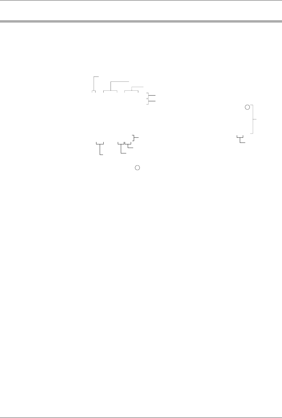
Figure D-25
An Example of the Intel Hex-32
Format
00-Data Record
This record begins with the colon start character, which is followed by
the byte count (in hex notation), the address of the first data byte, and the
record type (equal to 00). Following these are the data bytes. The
checksum follows the data bytes and is the two’s complement (in binary)
of the preceding bytes in the record, including the byte count, address,
record type, and data bytes.
01-End Record
This end-of-file record also begins with the colon start character and is
followed by the byte count (equal to 00), the address (equal to 0000), the
record type (equal to 01), and the checksum, FF.
02-Extended Segment
Address Record
This is added to the offset to determine the absolute destination address.
The address field for this record must contain ASCII zeros (Hex 30s).
This record type defines bits 4 to 19 of the segment base address. It can
appear randomly anywhere within the object file and affects the absolute
memory address of subsequent data records in the file. The following
example illustrates how the extended segment address is used to
determine a byte address.
:020000020000FC
:020000040010EA
:10000000FFFFFFFFFFFFFFFFFFFFFFFFFFFFFFFF00
:10001000FFFFFFFFFFFFFFFFFFFFFFFFFFFFFFFFF0
:10002000FFFFFFFFFFFFFFFFFFFFFFFFFFFFFFFFE0
:10003000FFFFFFFFFFFFFFFFFFFFFFFFFFFFFFFFD0
:10004000FFFFFFFFFFFFFFFFFFFFFFFFFFFFFFFFC0
:00000001FF
Offset Address
Address
Start Character
Extended Segment Address Record
Extended Linear Address Record
Data
Records
End-of-File Record
Checksum
Record Type
Byte
Count
Nonprinting Carriage Return, with optional
line feed and nulls determined by null count
LEGEND
0433-3
Checksum