2500_Users_Manual - 第423页
Local M ode ProM aster 25 00 User Manua l F-1 1 The 2500 displays : Enter a number from 0 t o 254. Entering a “0 ” (zero) places t he left end of the label on the leadin g edge of the device; each unit high er moves the …
Local Mode
F-10 ProMaster 2500 User Manual
Labeler Setup Menu
This menu allows you to alter parameters which affect the printing of
characters on a label and the application of that label on a device.
Label Calibration
Label calibration determines the distance between the edge of the label
and the first printed character. If characters are not being printed on the
label with the correct spacing from the label’s edge, make sure that the
following have been checked:
• Labels have been calibrated.
• Labeler’s pinch rollers are fully engaged against the drive roller.
• ADC value is correctly set to 200.
Note: When you are running a Task or performing any other handler operation,
it is best to use the Stop command
LOWER CASE
+
C
for this parameter.
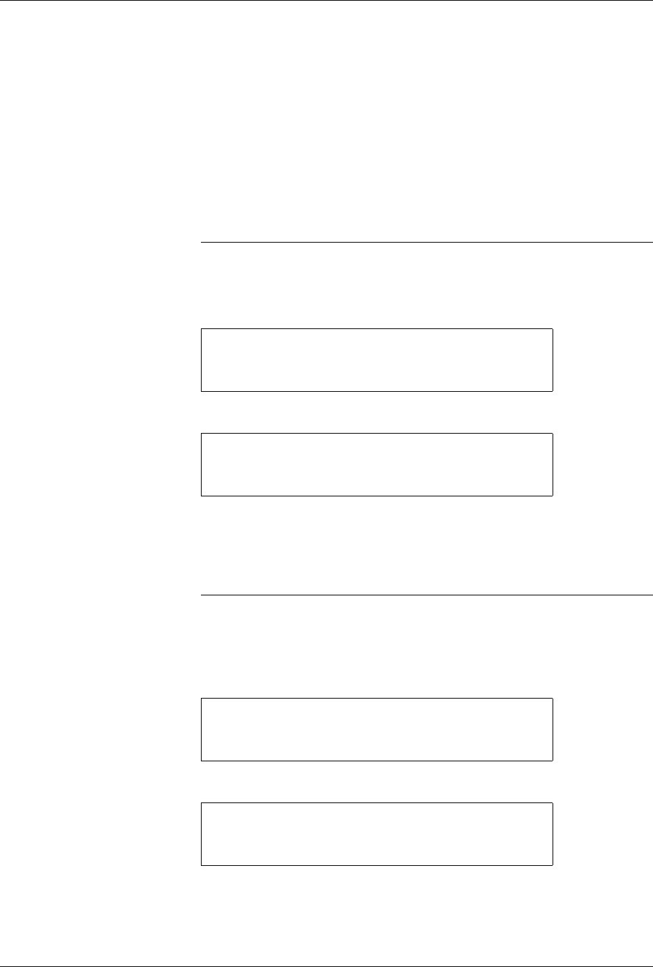
To change the current label calibration value from the 2500’s front panel,
put the 2500 in local mode. Press
1
from the Labeler Setup menu.
The 2500 displays:
Use the 2500’s keyboard to change the setting. The range is from 0 to 255.
After entering the desired value, save it by pressing the ENTER key. The
2500 records this value as the new default and returns to the Labeler
Setup menu.
Note: If you change the label calibration value, press the CAL key so that the
ADC optic performs the ADC optic label calibration.
Label Placement
The label placement default setting centers the label on the device.
Change this setting from the 2500’s front panel by first putting the system
in local mode. From the Main Menu, press
3
.
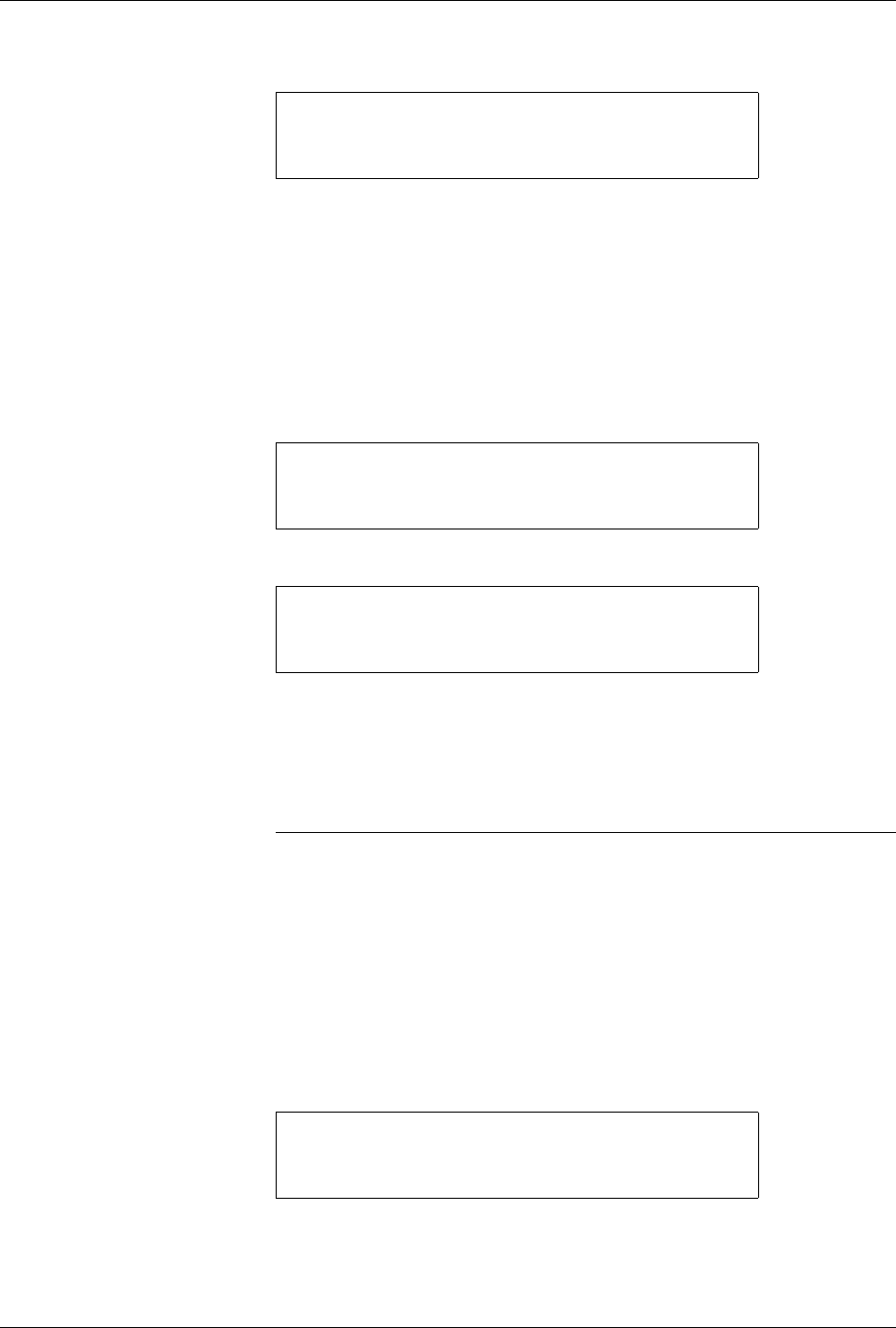
From the Labeler Setup menu, press
2
to select LABEL PLACEMENT.
* * * LABELER SETUP MENU * * *
1 - LABEL CALIBRATION 4 - SETUP MENU
2 - LABEL PLACEMENT
3 - LABEL ADJUST
ENTER LABEL CALIBRATION VALUE (XX):_
* * PROMASTER 2500 MAIN MENU * *
ENTER THE NUMBER OF THE DESIRED FUNCTION
1 - OPERATIONS 3 - SYSTEM SETUP
2 - FILE UTILITIES 4 - DIAGNOSTICS
* * * LABELER SETUP MENU * * *
1 - LABEL CALIBRATION 4 - SETUP MENU
2 - LABEL PLACEMENT
3 - LABEL ADJUST
Local Mode
ProMaster 2500 User Manual F-11
The 2500 displays:
Enter a number from 0 to 254. Entering a “0” (zero) places the left end of
the label on the leading edge of the device; each unit higher moves the
label 0.010-inches away from the leading edge of the device. Press
ENTER
to accept the selection.
This parameter can also be changed by the system administrator using
TaskLink.
Label Adjust
This is a fine-tune adjustment for the label placement value when it is set
to “autocenter.” To change the value when the 2500 is in the local mode,
go to the Labeler Setup menu and press
3
.
The 2500 displays:
Use the 2500’s key pad to change the displayed setting. Increasing the
number moves the label farther from the leading edge of the device.
When you have entered the desired value, save it by pressing
ENTER
.
The 2500 records this value as the new default and returns to the Labeler
Setup menu.
Note: When you are running a Task or performing any other handler operation,
it is best to use the Stop command
LOWER CASE
+
C
for this parameter.
Handler Menu
The items in this menu allow you to alter parameters affecting the
handling of devices on the 2500.
Binning
The binning assignments defined by this command are used to redefine
which output tube on the 2500 will receive the pass and fail devices after
the programming operation. Under normal circumstances these will not
be changed from the factory defaults.
If it should become necessary to change the bin assignments, press
3
from
the System Setup menu to select HANDLER.
ENTER LABEL PLACEMENT VALUE (X):
ENTER "A" FOR AUTO CENTERING
* * * LABELER SETUP MENU * * *
1 - LABEL CALIBRATION 4 - SETUP MENU
2 - LABEL PLACEMENT
3 - LABEL ADJUST
ENTER LABEL ADJUST VALUE (X): _
* * * SYSTEM SETUP MENU * * *
1 - GENERAL 4 - MAIN MENU
2 - LABELER
3 - HANDLER

Local Mode
F-12 ProMaster 2500 User Manual
The 2500 displays:
Press
1
. The 2500 displays:
The
C
in the displays represents the category signal sent by TaskLink (or
any computer remote control driver program) to indicate the result of the
last programming operation. In the example above, a
C1
signal from
TaskLink indicates that the device passed.
BIN 1
represents output tube
holder 1 and
BIN 2
represents output tube holder 2. When TaskLink send
a C1 signal, the 2500’s beam takes the device to the labeler (if the Task has
label selected as part of the current process) and then places that device in
output track 1.
For a device that has had a programming error, TaskLink might be
configured to send a C2 to the 2500. The 2500 would not label the failed
device and would send it to output bin 2, which is output tube 2.
This is the default setting for the binning control setup. Notice that in the
second line for all failures, there is no
X
after
Label
in the second line of
the display above. If labeling has been selected in the Task, this
unselected option instructs the 2500 not to label a device that has failed. If
you find that the 2500 is labeling failed devices, check to see that someone
has not inadvertently placed an X after Label in the second line. The 2500
will not label passing devices with one label text and failing devices with
different label text.
Control Functions
This command is used in conjunction with the Program/Test Only and
Program/Test and Label commands under the Operations menu. These
commands are used by Data I/O service personnel only and are not
usable under normal operation.
* * * HANDLER SETUP MENU * * *
1 - BINNING
2 - CONTROL FUNCTIONS
3 - SETUP MENU
BIN 1=C1-X C2- C3- C4- C5- LABEL-X
BIN 2=C1- C2-X C3-X C4-X C5-X LABEL-