2500_Users_Manual - 第48页
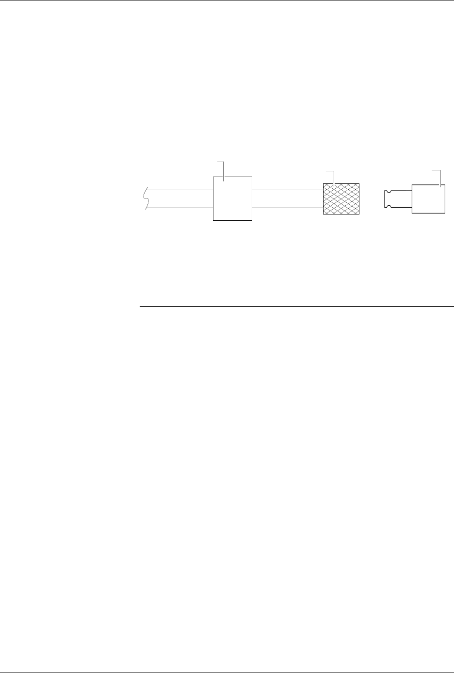
Insta llation a nd Se tup ProM aster 25 00 User Manua l 2-5 2. Pul l the sliding knurled sleeve back and in sert one of the male q uick connects. 3. Release the knurled sleeve and check the connection to ensure that it i…
Installation and Setup
2-4 ProMaster 2500 User Manual
• An input air line (6 ft) with a male 1/4-inch NPT adapter on one end
• Two male quick connects with female 1/4-inch NPT adapter on one
end
•Label roll
•Chuck set
•Spares Kit
•Power cord
•
ProMaster 2500 User Manual
with End User Registration Card
• Customer letter
Installing the 2500
This section describes installing various components on the 2500 to
prepare it for operation. Power to the 2500 should be off during these
steps.
Selecting the Correct
Adapter
Perform the following procedure to determine which of the two male
quick connects provided with the system is correct for the female quick
connect on your source air line.
1. Turn the external air source off so the source air line is not
pressurized.
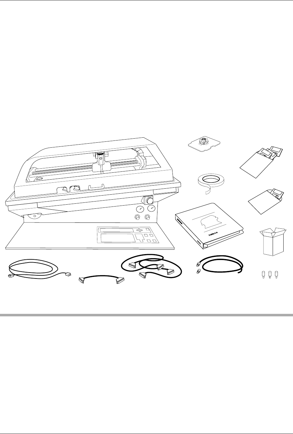
Figure 2-3
System Contents
PROMASTER 2500
DISKS
POWER CORD
USER
MANUAL
1763-3
RS-232 CABLE (2)
ProMaster 2500
TASKLINK
DISK
LABEL
ROLL
1/4" INPUT AIR LINE
(With 2 adapters)
PROGRAMMING
MODULE
9 - 25 PIN
CABLE
SPARES KIT
CHUCK SET
Installation and Setup
ProMaster 2500 User Manual 2-5
2. Pull the sliding knurled sleeve back and insert one of the male quick
connects.
3. Release the knurled sleeve and check the connection to ensure that it
is locked in place and seated correctly. Only one of the two male
quick connects will seat correctly with the female connector you have
on your source air line (see Figure 2-4).
4. Remove the male quick connect by pulling back the knurled sleeve. If
necessary, repeat this process with the other male connector to
identify the appropriate mating piece.
Connecting the
Input Air Line
The ProMaster 2500 needs a clean, dry, filtered, oil-free input air source.
Follow these steps to connect your external air source to the 2500.
CAUTION: Oil, excessive moisture, or poorly filtered input air will
affect the performance of the system and will void the
warranty on the air circuits.
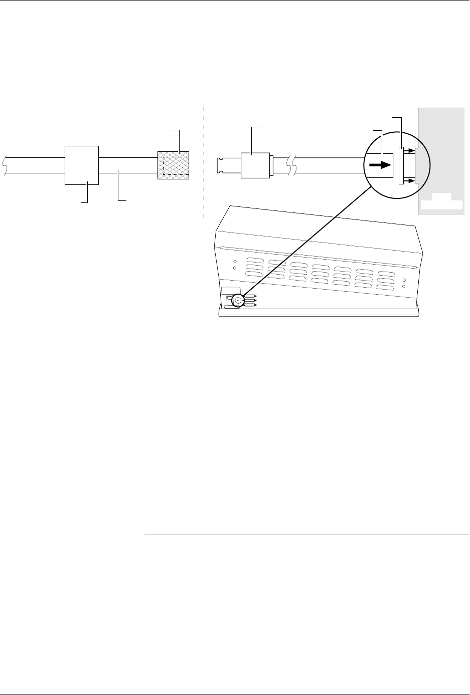
1. Insert the plastic end of the air line (the end without the 1/4-inch
NPT adapter) through the 2500’s air input collar (see Figure 2-5).
2. Screw the appropriate male quick connect on the 1/4-inch NPT
adapter on the input air line that is supplied with the system.
3. Connect the source air line to the 2500 by pulling back the knurled
sleeve and inserting the male quick connect, releasing the sleeve at
the same time as the male end is fully inserted.
4. Turn on the system air and make sure that your external regulator is
set to 80 PSI (5.5 bar).
Figure 2-4
Selecting the Correct Quick
Connect
MALE QUICK CONNECT
(With female 1/4 NPT)
FEMALE QUICK CONNECT
(Knurled Sleeve)
1957-1
FILTER/REGULATOR
Installation and Setup
2-6 ProMaster 2500 User Manual
5. The 2500’s high and low air pressure gauges will immediately
display their current settings. Adjust these by performing the
procedure on page 2-7.
Disconnecting the
Source Air Line from
the 2500
Follow these steps to open the air connection between the external source
and the 2500:
1. Hold the air lines on either side of the knurled sleeve.
2. Pull back the knurled sleeve. The air pressure from your external
source will separate the two pieces.
Removing the Input
Air Line from the
2500
To cut off the air from the 2500, follow this procedure.
Note: When you remove the system air from the 2500, disconnect the input air
line where it connects at the knurled sleeve to your air source before you
remove the air line from the back of the 2500.
1. Ensure that the 2500’s air line is disconnected from the source air line
at the knurled quick connect.
2. Push the air input’s collar on the 2500 against the 2500’s body to
release its hold on the input air line (see Figure 2-5).
3. Continue to push the collar against the 2500’s body, and pull the air
line out of the 2500.
Figure 2-5
Connecting the External Air to the 2500
AIR LINE
MALE QUICK
CONNECT
FEMALE QUICK CONNECT
SOURCE AIR LINE
FILTER/REGULATOR
TO EXTERNAL
AIR SOURCE
SUPPLIED BY CUSTOMER DELIVERED WITH PROMASTER
1956-1
COLLAR
2500
SIDE VIEW