2500_Users_Manual - 第57页
Insta llatio n and Se tup 2-14 ProMa ster 25 00 U ser Ma nual Calibrati ng Labels The label optic mus t be calibrated to detect and synchronize w ith the labels after you have fini shed any of the follo wing op erations:…

Installation and Setup
ProMaster 2500 User Manual 2-13
Setting Up the
Thermal Printer
Before labels can be printed and applied to processed devices, the label
and ribbon material must first be loaded. The following sections cover
the correct procedures for loading and calibrating labels and loading a
new ribbon and repairing a torn ribbon.
Loading Labels
Threading labels on the thermal labeler is similar to threading labels on
the dot matrix labeler (see Figure 2-11). The major difference on the
thermal printer is that the retractable rollers (platen pinch and label pinch
rollers) snap back into position if you release them. On the dot matrix
labeler, the rollers remain in the open position.
Note: Do not tighten the label roll on its core. The roll is intentionally loose so
the combination of high temperature and humidity do not cause the labels
to peel incorrectly.
Follow this procedure to load a new roll of labels.
1. Push the label pinch roller and the platen pinch rollers into their
retracted positions away from the platen.
2. Remove the magnetic cover from the label roll.
3. Install the new label roll on the label supply hub so that the leader
comes off from the right side of the hub (see Figure 2-11).
4. Mount the magnetic cover over the label roll to hold the labels in
place.
5. Prepare the label path by raising the application plate and retracting
the platen pinch and label pinch rollers.
6. Thread about 2 feet (60 cm) of label liner around the left side of the
label alignment roller and through the gap between the application
plate and the output track. Lay the liner along the output track for the
time being.
7. Position the label liner on the underside of the platen and guide the
platen pinch roller back into its operating position against the platen
to hold the liner in place.
8. Thread the liner between the ADC optic and the platen, and then
between the print head and the platen.
9. Make sure that the label liner is flat against the underside of the
platen.
10. Feed the liner back over the top of the platen and through the gap
between the platen and the track.
11. Thread it between the label drive roller and the label pinch roller (see
Figure 2-11).
12. Thread the liner between it and the drive roller. Guide the spring-
loaded pinch roller back into its operating position against the drive
roller. Make certain that there is no slack in the liner.
13. Lower the label application plate.
This completes the installation procedure. Be sure to calibrate the labels
as described in the next section before attempting to label devices.
Installation and Setup
2-14 ProMaster 2500 User Manual
Calibrating Labels
The label optic must be calibrated to detect and synchronize with the
labels after you have finished any of the following operations:
• Installing a new roll of labels
• Changing the ribbon
• Adjusting the ADC reference value
• Manually moving the labels
Perform the following steps to calibrate the labels.
1. Put your finger near the label application point (the right edge of the
application plate).
2. Press
CAL
on the front panel of the 2500.
3. Use your finger to catch the three or four labels ejected while the
labels are being calibrated.
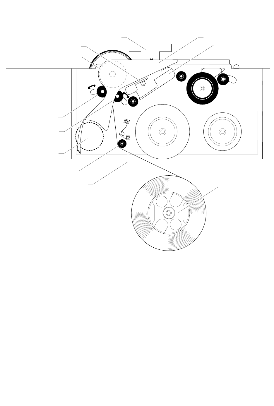
Figure 2-11
Threading Labels in the Thermal Printer
2303-1
LABEL DRIVE ROLLER (hidden)
LABEL PINCH ROLLER
LABEL ADVANCE KNOB
LABEL ALIGNMENT ROLLER
LABEL DETECTION OPTIC
LABEL ROLL
(cover removed)
APPLICATION PLATE (raised)
PLATEN
PRINT HEAD
(retracted position)
LABEL ADC OPTIC
PLATEN PINCH ROLLER
Installation and Setup
ProMaster 2500 User Manual 2-15
Installing a New Ribbon
Each new ribbon roll has a long leader to thread through the labeler.
Follow the procedure below to install the new ribbon (refer to Figure
2-12).
1. Prepare the ribbon threading path by pushing the ribbon pinch roller
to the right.
2. Install the ribbon take-up core (one empty core is supplied with the
printer) on the ribbon take-up hub. After threading the ribbon, you
will tape the ribbon’s leader to this cardboard core.
3. Thread the ribbon leader over ribbon alignment roller 1, over the
print head, and over ribbon alignment roller 2.
4. Thread the ribbon leader under the ribbon drive roller, over the
ribbon pinch roller, and down to the ribbon take-up roll (see Figure
2-12).
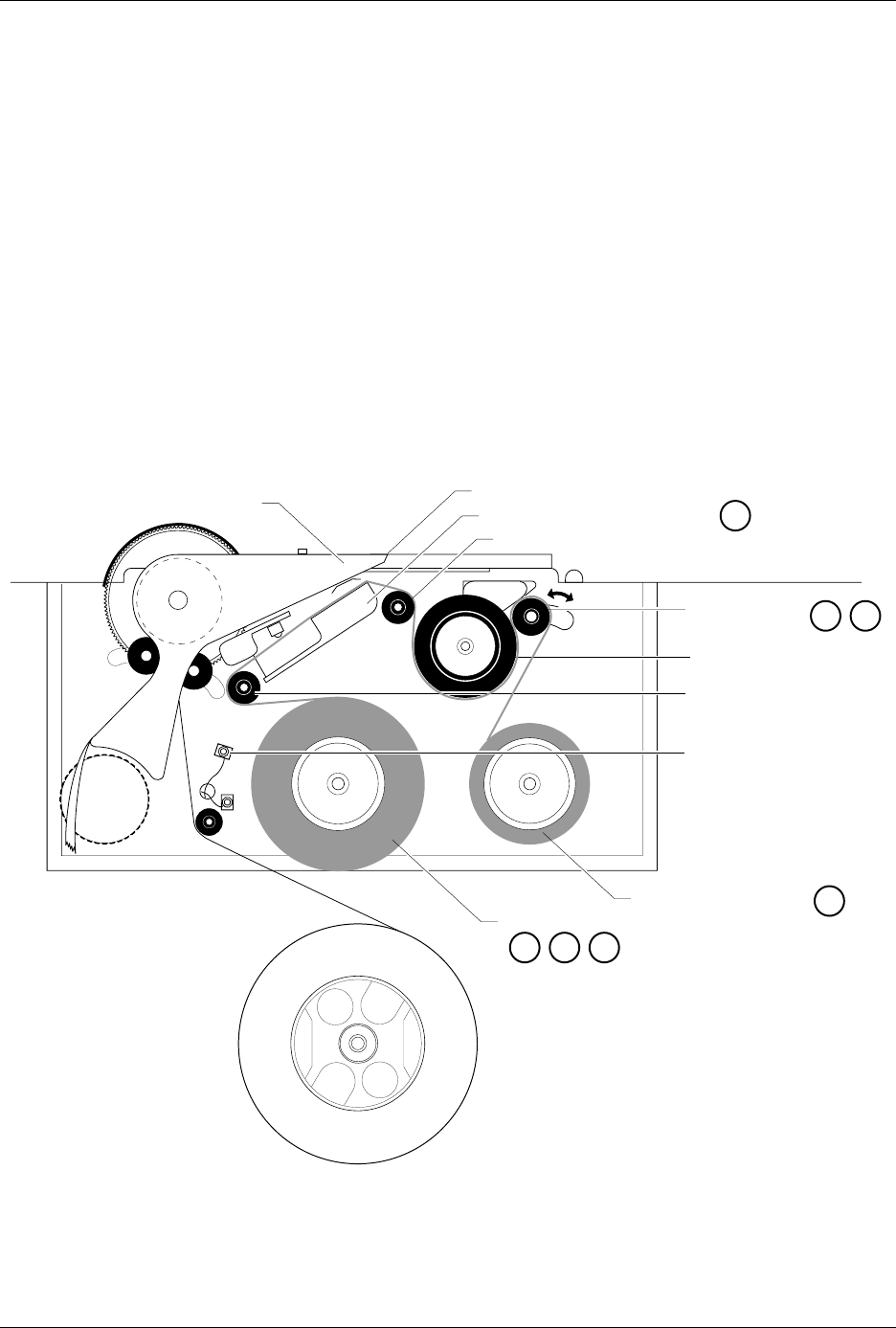
Figure 2-12
Threading a Ribbon in the Thermal Printer
2304-2
PRINT HEAD (Retracted position)
RIBBON ALIGNMENT ROLLER 2
RIBBON ALIGNMENT
ROLLER 1
RIBBON DETECT OPTIC
RIBBON ROLL
RIBBON PINCH
ROLLER
RIBBON DRIVE ROLLER
PLATEN
RIBBON TAKE-UP ROLL
APPLICATION AREA
123
4
56
8