2500_Users_Manual - 第58页
Insta llation a nd Se tup ProM aster 25 00 User Manua l 2-15 Installing a New Ribbon Each new ribbon roll has a long lead er to thread through the labeler. Follow the pro cedure below to ins tall the new ribbo n (refer t…
Installation and Setup
2-14 ProMaster 2500 User Manual
Calibrating Labels
The label optic must be calibrated to detect and synchronize with the
labels after you have finished any of the following operations:
• Installing a new roll of labels
• Changing the ribbon
• Adjusting the ADC reference value
• Manually moving the labels
Perform the following steps to calibrate the labels.
1. Put your finger near the label application point (the right edge of the
application plate).
2. Press
CAL
on the front panel of the 2500.
3. Use your finger to catch the three or four labels ejected while the
labels are being calibrated.
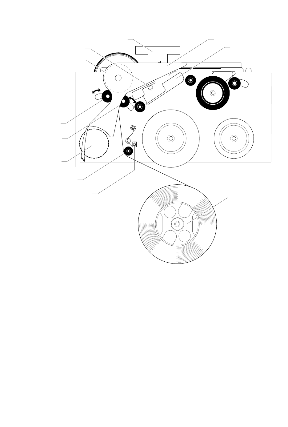
Figure 2-11
Threading Labels in the Thermal Printer
2303-1
LABEL DRIVE ROLLER (hidden)
LABEL PINCH ROLLER
LABEL ADVANCE KNOB
LABEL ALIGNMENT ROLLER
LABEL DETECTION OPTIC
LABEL ROLL
(cover removed)
APPLICATION PLATE (raised)
PLATEN
PRINT HEAD
(retracted position)
LABEL ADC OPTIC
PLATEN PINCH ROLLER
Installation and Setup
ProMaster 2500 User Manual 2-15
Installing a New Ribbon
Each new ribbon roll has a long leader to thread through the labeler.
Follow the procedure below to install the new ribbon (refer to Figure
2-12).
1. Prepare the ribbon threading path by pushing the ribbon pinch roller
to the right.
2. Install the ribbon take-up core (one empty core is supplied with the
printer) on the ribbon take-up hub. After threading the ribbon, you
will tape the ribbon’s leader to this cardboard core.
3. Thread the ribbon leader over ribbon alignment roller 1, over the
print head, and over ribbon alignment roller 2.
4. Thread the ribbon leader under the ribbon drive roller, over the
ribbon pinch roller, and down to the ribbon take-up roll (see Figure
2-12).
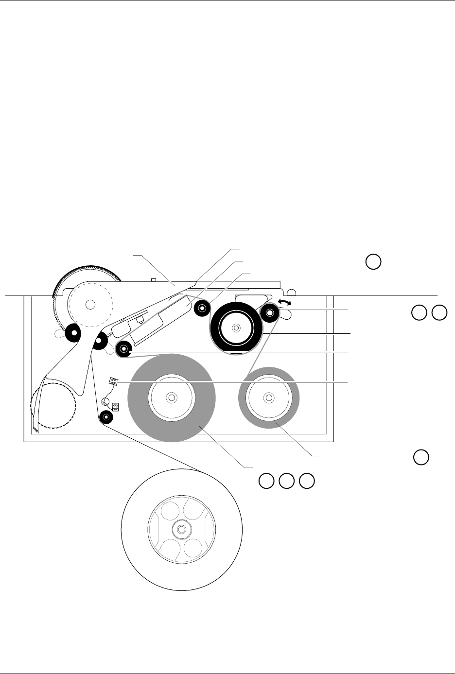
Figure 2-12
Threading a Ribbon in the Thermal Printer
2304-2
PRINT HEAD (Retracted position)
RIBBON ALIGNMENT ROLLER 2
RIBBON ALIGNMENT
ROLLER 1
RIBBON DETECT OPTIC
RIBBON ROLL
RIBBON PINCH
ROLLER
RIBBON DRIVE ROLLER
PLATEN
RIBBON TAKE-UP ROLL
APPLICATION AREA
123
4
56
8

Installation and Setup
2-16 ProMaster 2500 User Manual
5. Guide the pinch roller back into its operating position against the
drive roller.
6. Use the tape supplied on the end of the leader (or a DIP label) to
attach the leader to the take-up cardboard core.
7. When you install a new ribbon, remove the old ribbon’s cardboard
core and install it on the take-up hub as the new ribbon take-up core.
8. Turn the ribbon take-up roll counterclockwise to advance the ribbon
until it (not the leader) is between the print head and the platen.
Repairing a Torn Ribbon
Under normal circumstances you should not have a problem with the
ribbon tearing. If it does tear, follow the procedure below to repair it.
1. Cut the end of the ribbon to remove the tear and create a straight end.
2. Cut about 16 inches (40 cm) of old label liner (hanging from the label
drive roller) to use as ribbon leader.
3. Line up the end of the ribbon with the end of the liner and tape the
two ends together (a DIP label can also be used as a tape splice).
4. Turn the splice over and tape the other side.
5. Wrap the liner around the ribbon roll once, and then follow the
instructions for installing a new ribbon. If the ribbon begins to slide
off the roll while you are threading, place a large label across the edge
of the ribbon roll to stop the unraveling. Remove this label when you
have finished threading and before you start processing devices.
Connecting the PC and Installing TaskLink
Before you start creating Tasks using TaskLink, you will need to:
1. Connect the RS-232C cables between the PC and the 2500.
2. Install TaskLink on the PC.
3. Start the program.
Connecting the PC
Connect the 2500 to the two PC COM ports using the cables provided
with the system. The cables are the same type and can be used on either
port on the 2500.
1. Connect one of the serial cables to the COM1 serial port on the back
of your PC. TaskLink uses COM1 as the default programmer port.
Note: If your PC has a 9-pin connector, use the 9-pin adapter included with the
system to connect the data cable to your PC.
2. Connect the other end of the COM1 cable to the connector labeled
Programmer Port
on the back of the 2500.