2500_Users_Manual - 第72页
Insta llation a nd Se tup ProM aster 25 00 User Manua l 2-29 Adjusting the Print Intensity of the Thermal Printer You can ch ange the factory default settin g for print i ntensity by using th e STOP comma nd while th e 2…
Installation and Setup
2-28 ProMaster 2500 User Manual
Print Shift
Change this value using the STOP command described in the following
procedure.
1. Press
STOP
to pause the 2500 while a Task is running.
2. Press
LOWER CASE
+
P
. The display on the 2500 prompts you to
enter a new value.
3. Press
↑
and
↓
to enter a new print shift value between 0 and 16.
Entering a larger numeric value moves the printed character higher
on the label.
4. Press
START
to continue running the Task.
Label Calibration
Change the label calibration value using the STOP command described in
the following procedure:
1. Press
STOP
to pause the 2500 while a Task is running.
2. Press
LOWER CASE
+
C
. The 2500 displays:
where
XXX
represents a numeric value for the current setting.
3. Press
↑
and
↓
to change the label calibration value (the range is from
0 to 255). Entering a larger numeric value moves the printed
characters closer to the leading edge of the label.
4. Press
START
to continue running the Task.
Label Advance
The label advance value defines how far a label extends above the
application plate before it is applied to a device.
The value can be changed by pressing
STOP
and
LOWER CASE
+
W
.
Increasing the numeric value advances the label farther above the
application plate.
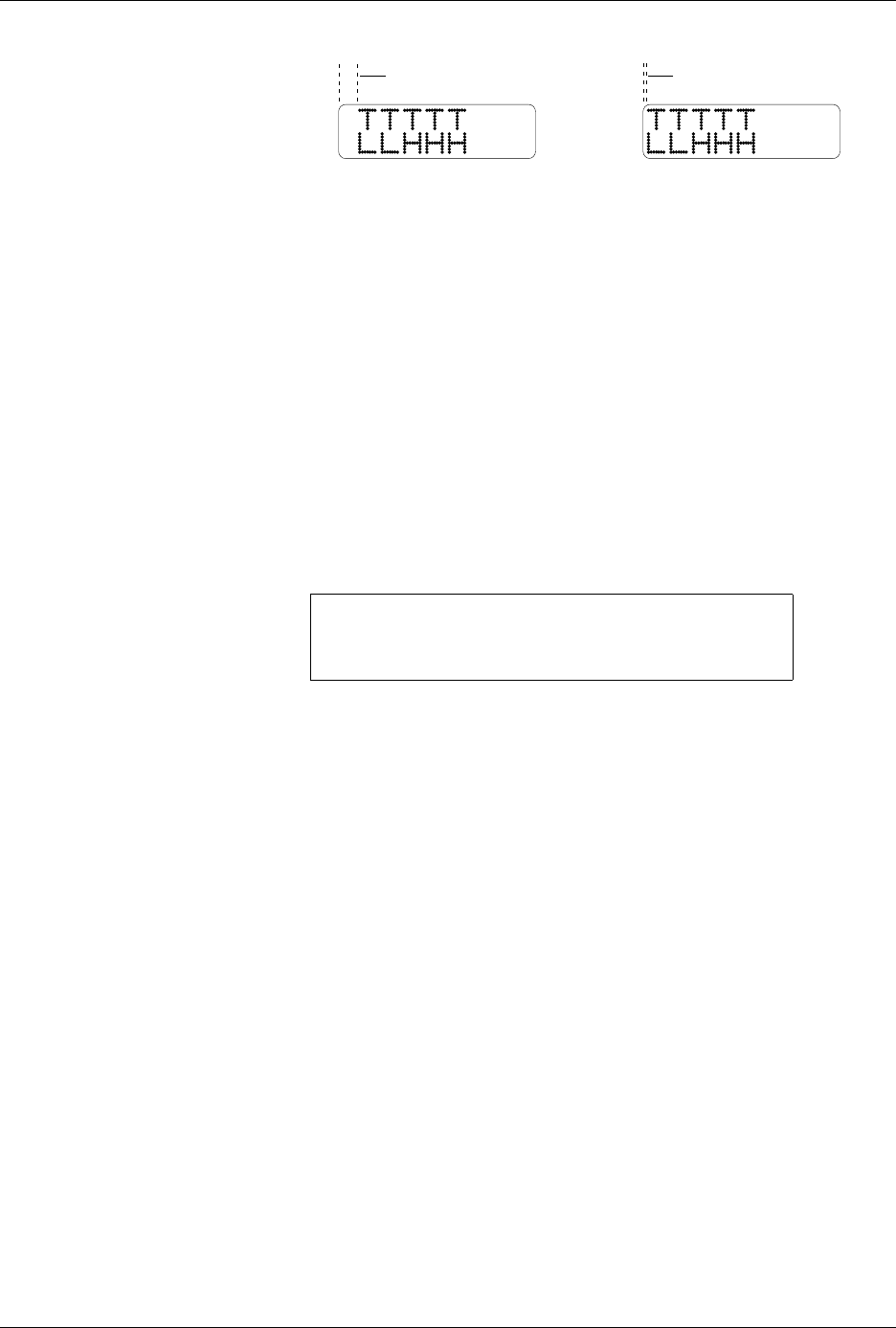
Figure 2-19
Label Calibration
(affects horizontal position)
PROGRAM/TEST LABEL
SLAVE MODE PART TYPE: DIP 24-.3
PART TOTAL: 251 PART LENGTH: 1.250
LABEL CAL: (XXX)
2177-1
NORMAL
HIGHER VALUE

Installation and Setup
ProMaster 2500 User Manual 2-29
Adjusting the Print
Intensity of the
Thermal Printer
You can change the factory default setting for print intensity by using the
STOP command while the 2500 is processing devices.
Note: The print head uses more energy when the intensity value is increased.
The life expectancy for the print head is shorter when this setting is set to
a high value. Select a print intensity value that produces a legible label
while not creating excessive wear.
The range for intensity is from 1 to 21. The darkest character is printed
when intensity is set to 21.
Follow the procedure below to change the current thermal intensity
value.
1. Press
STOP
. The 2500 pauses while it is running a Task.
2. Press
LOWER CASE
+
I
. The display on the 2500 prompts you to
enter a new value.
3. Press
↑
and
↓
to enter a new thermal intensity value between 1 and 21
(as described above).
4. Press
START
to continue running the Task.
Updating the 2500
Three different updates are periodically distributed for the 2500:
•
ProMaster 2500 Algorithm/System Software
— This software
updates the programming algorithms and the programming
electronics system files. It is installed from update disks inserted in
the 2500’s disk drive.
•
TaskLink Software
— This update to TaskLink is inserted in the PC’s
floppy disk drive and installed onto the hard drive.
•
Firmware
— This is an EPROM update of the operating system
firmware on the 2500 controller board.
The installation procedures for the Algorithm/System and TaskLink
software updates are included with the User Notes that are distributed
periodically. The firmware update installation procedures are described
in the following section (see Figures 2-20 and C-2).
ENTER THERMAL INTENSITY (X):

Installation and Setup
2-30 ProMaster 2500 User Manual
Installing a 2500
Firmware Update
The 2500 firmware will be updated periodically to add new operating
features. The update replaces the EPROM in location
U15
and/or
U43
on
the handler controller board.
CAUTION: To avoid possible damage to the system components, this
procedure should be performed only by a qualified service
technician. Observe all antistatic precautions while
performing this operation.
Follow these steps to install a firmware update to the 2500. To reduce or
prevent possible damage to these static-sensitive devices from ESD, wear
your antistatic wrist strap when performing this procedure.
1. Turn off the 2500 and remove the power cord.
2. Remove all devices from the tracks and all tubes from the tube
holders.
3. Unscrew the two corner screws that hold the main plate to the 2500’s
base.
4. Lift the main plate to expose the 2500’s interior, and remove the
internal device shield.
WARNING:To prevent the hood or main plate from accidentally
falling shut, be careful not to jar the 2500 when they are
raised.
5. Locate the U15/U43 EPROM on the handler controller board (refer to
the controller board layout in Figure 2-20 and Appendix C).
6. Use an IC remover tool to carefully remove the current DIP firmware
device from its socket.
7. Install the new firmware device in the socket, being careful not to
bend any of the device leads. Make sure that pin 1 is properly
oriented.