2500_Users_Manual - 第97页
Task s and Ki ts 3-22 ProMa ster 25 00 U ser Ma nual Serializ ing Devices You may wan t to program a serial number into the devices and/or print the number on the label. TaskLink’s Serializa tion... option offers an oppo…
Tasks and Kits
ProMaster 2500 User Manual 3-21
Remote Control commands in Appendix E.
For example, you might use these commands if you want to program a
device but disable the verify option. The Edit Task dialog box does not
allow you to select this combination. From that box, Verify is
automatically enabled when Program is selected. Use the
023]
command
to disable the verify operation.
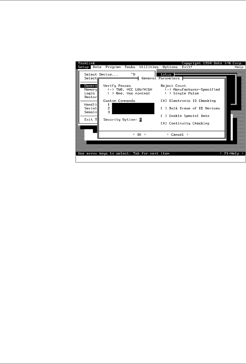
Security Option
— Some devices have a security fuse that, when
programmed, prevents any programming equipment from reading its
data. Set this value to 3 to program the security fuse in most PLD devices.
The main array of device fuses are verified before the security fuse is
programmed. If the main array fuses pass, the security fuse is
programmed and the 2500 will no longer be able to read the original
sumcheck from the device. The only way to confirm correct data in a
device after its security fuse has been programmed is to run structured test
vectors.
Enable Special Data
— Used by some devices to enable special options
they offer. The option depends on the device being programmed. For
example, some microcontroller devices have extra security fuses that can
be enabled only when this parameter is set. Refer to the 2500 Device List
footnotes to see if any special options are available for the device in your
Task.
Continuity Checking
— This option allows you to enable or disable
continuity checking on some devices. Under most circumstances you
would not disable this check as it provides important information about
how the device is seated in the programming module. If the test is
disabled and a device is not making good contact in the programming
module, the device will fail with either a programming or verify error. For
some devices, the continuity test is an integral part of the programming
algorithm and cannot be disabled even when it is not selected on the
screen. Continuity checking is enabled when TaskLink is shipped.
Figure 3-14
General Parameters Dialog Box

Tasks and Kits
3-22 ProMaster 2500 User Manual
Serializing Devices
You may want to program a serial number into the devices and/or print
the number on the label. TaskLink’s
Serialization...
option offers an
opportunity to do this in software. A sample serialization program called
serializ.exe
is provided with TaskLink. For detailed information on the
serialization program, refer to the External Serialization Program section
on page 3-25 and to the online help topic “Writing a Serialization
Program” under TaskLink’s General Help Index. To implement
serialization features not provided by
serializ.exe
, you will need to write
a short external serialization program (ESP) to generate your serial
number and save it in an ASCII file for TaskLink to use.
To print a serial number on a label, enter a percent sign (%) in the label
text field (ProMaster 2500 dialog box) for each character to be printed on
the label (refer to the command line length parameter “-l”).
Note: You must have U15 version 1.06 or greater to print a serial number.
Figure 3-16 shows the process steps in creating a file to be used for
serializing devices.
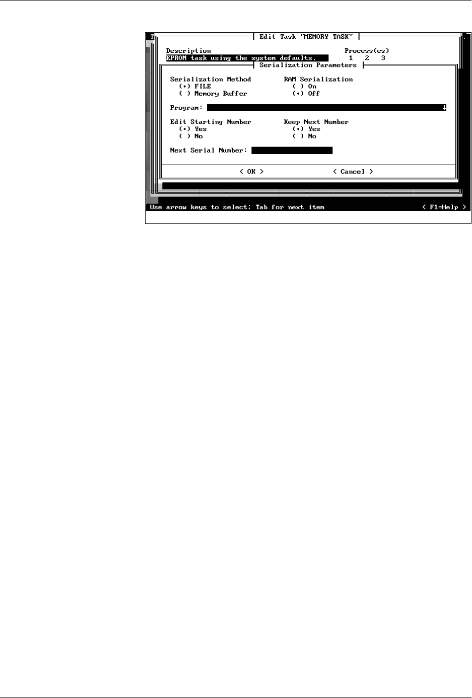
The
Program
line in TaskLink’s
Serialization Parameters
screen (see
Figure 3-15) allows you to enter the executable name for your external
program (ESP). You can also include the path and command line
arguments that define the characteristics of the serial number to pass to
the ESP. The ESP is called from the command line using a command
similar to the following:
drive:\path\file_name
where
drive
is the drive where the ESP resides,
path
is a valid DOS path
to the subdirectory where the ESP is written, and
file_name
is the ESP
executable file name and extension.
Tasks and Kits
ProMaster 2500 User Manual 3-23
Serialization Method —
select
File
when operating with an ESP. (The
Memory Buffer selection is offered to maintain compatibility with a
previous product and should not be used to create a new ESP.)
RAM Serialization
— select
On
when you want the serial number to be
programmed in the device. Selecting
Off
will print the serial number on
the label when you have included two or more percent (
%
) signs in a row
in the label text field (in the
ProMaster 2500
dialog box).
Edit Starting Number
— set to
Yes
when the starting serial number will
be entered or edited by the operator at the start of the Task. Enter the new
serial number in the Next Serial Number field.
TaskLink will record the last serial number programmed into a device,
increment it, and use it as the starting number the next time the Task is
run. Select
No
if you want to operate in this manner.
Keep Next Number
— select
Yes
if you want TaskLink to record the next
valid serial number so it can be used the next time the Task is run. If the
last successfully programmed and serialized device had a serial number
of 7123, selecting
Yes
would program serial number 7124 into the first
device on the next run of the Task.
When this dialog box is complete, move the cursor to
<OK>
and press
↵
.
TaskLink calls the ESP program (see Figure 3-16) when the Task is run,
before the first device is processed. The ESP generates a valid serial
number, creates an ASCII file called
Serial.dat
and writes it on the PC’s
disk. The ESP passes control back to TaskLink. The serial number file is
downloaded to the 2500’s RAM, and the device is programmed.
Figure 3-15
Serialization Parameters Dialog
Box