SM-131-006.pdf - 第105页
Device Name Chip Mounter Block Name Page No. Unit Name Revision Model Item GXH-1 2. Replacement of Linear Measure Sensor Chapter 5 Head Section Linear Measure Sensor 2.1 Detachment of Linear Measure Sensors (1) Remove th…

Device
Name
Chip Mounter
Block Name
Page No.
Unit Name
Revision
Model ItemGXH-1
Chapter 5 Head Section
1. Replacement of Head Unit
1.3 Operation Check
Check if the power can be supplied normally and the zeroing and manual axis operations
can be performed normally.
Check the connection of the pneumatic and vacuum pipes.
1.4 Adjustment of Offsets
Adjust the following offset items.
1.4.1 Manual Offsets
(1) Head Up/Down Offset
(2) Feeder (A) Offset (L U/D)
1.4.2 Automatic Offsets
(1) Master Nozzle Level Offset
(2) PEC Recognition Camera & Beam Offset
(3) Component Recognition Camera Offset (Offset Teaching)
(4) Head Rotational Angle Axis Offset
(5) Head Rotational Center Offset/Reference Mark Position Offset
(6) Fly Recognition Camera Offset
(7) Nozzle Position Offset
(8) Nozzle Level Offset
(9) NL-Axis Origin Offset
0406-001
5-3
Device
Name
Chip Mounter
Block Name
Page No.
Unit Name
Revision
Model ItemGXH-1
2. Replacement of Linear Measure Sensor
Chapter 5 Head Section
Linear Measure Sensor
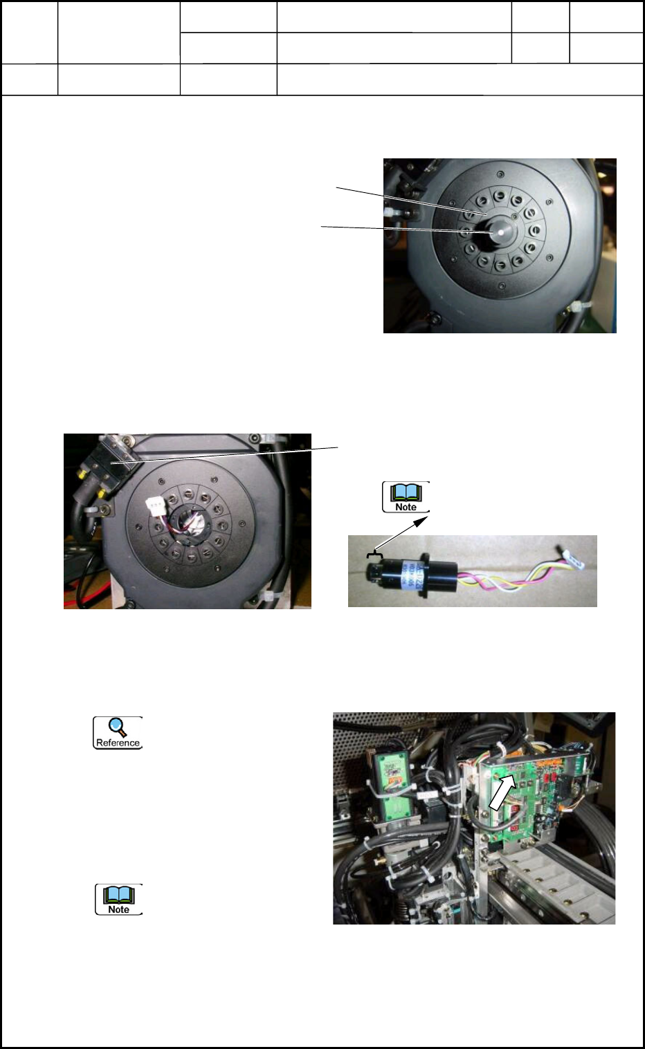
2.1 Detachment of Linear Measure Sensors
(1) Remove the two bolts (M1.6L5) of the
small diffusion plate (inner side)
(2) Remove the two bolts (M1.6L5) on the
light emitting side of the linear measure
sensor and detach the linear measure
sensor on the light emitting side from the
motor side.
Do not detach the linear measure sensor on the light receiving side.
Disconnect the linear measure sensors connected with the connectors. (Figs. E6 and E7)
(3) Detach the linear measure sensor amplifier board located beside the head (the upper
area of the head).
Heads #1 and #4 are
located inside and Heads
#2 and #3 outside.
Remove the three
connectors and the four
setscrews.
The linear measure
sensor amplifier board
and the linear measure
sensor on the light
emitting side are
assembled together (regarded as one unit). When it is required to replace either one
of them with a new one, be sure to replace both of them with new ones.
Fig. E5 Bottom Face of Head
Small Diffusion Plate
Linear Measure Sensor on
Light Emitting Side
Fig. E6 Detachment of Linear Measure
Sensor (Light Emitting Side)
Linear Measure Sensor on
Li
g
ht Receivin
g
Side
Fig. E7 Linear Measure Sensor on
Light Emitting Side
Do not make the glass side
dirty.
Fig. E8 Linear Measure Sensor Amplifier Board
(Example: Head #2)
0406-001
5-4
Device
Name
Chip Mounter
Block Name
Page No.
Unit Name
Revision
Model ItemGXH-1
2. Replacement of Linear Measure Sensor
Chapter 5 Head Section
Linear Measure Sensor
2.2 Attachment of Linear Measure Sensor
2.2.1 Attachment of Linear Measure Sensor on Light Emitting Side
Follow the reverse order of the steps described in "2.1 Detachment of Linear Measure
Sensors". When the linear measure sensor on the light emitting side is attached, be careful not
to make the bundled connector wires trapped (pinched).
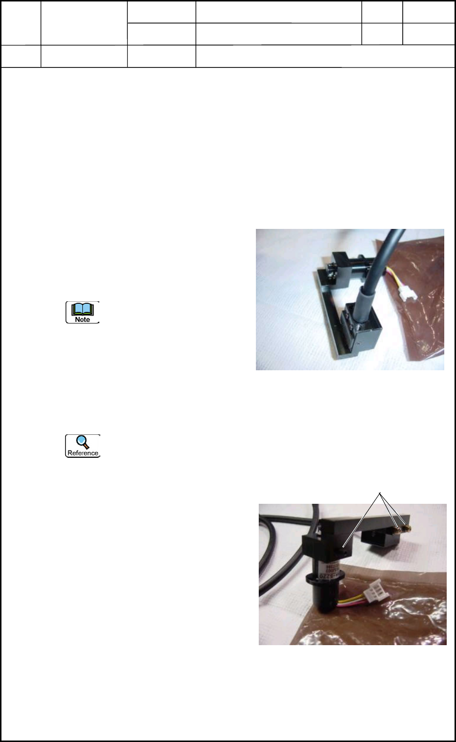
2.2.2 Attachment of Linear Measure Sensors on Light Emitting and
Receiving Sides
(1) A mounting jig is attached as shown in
Fig. E9 (the condition at the purchase).
Attach the linear measure sensor to the
DD motor side under this condition.
(a) Before the attachment, be
sure not to detach the sensor
from the mounting jig nor
loosen the bolts.
(b) Do not make the glass side
dirty.
Be sure not to make the wires trapped (pinched).
Light Emitting Side: M1.6L5 (2 pcs.)
Light Receiving Side: M3L8 sw and small fw (2 pcs.)
(2) After the linear measure sensor has been
attached, detach the mounting jig. (Fig.
E10)
(3) Attach the linear measure sensor
amplifier board.
(4) Connect the wires in the head section.
Re-bundle the wires on the light
receiving side and the wires running up
to the linear measure sensor amplifier
board.
2.3 Adjustment of Offsets
(1) Master Nozzle Level Offset (Offset: 0.5±0.1 mm)
(2) Nozzle Level Offset
Fig. E9 Mounting Jig
Remove these screws.
Fig. E10
0406-001
5-5