SM-131-006.pdf - 第117页
Device Name Chip Mounter Block Name Page No. Unit Name Revision Model Item GXH -1 Chapter 5 Head Section 4. Replacement of Nozzl e Shaft Nozzle Shaft Assembly 4.3.2 Assembly of Cam Foll ower Secti on Assem ble the cam fo…
Device
Name
Chip Mounter
Block Name
Page No.
Unit Name
Revision
Model Item GXH-1
Chapter 5 Head Section
4. Replacement of Nozzle Shaft
Nozzle Shaft Assembly
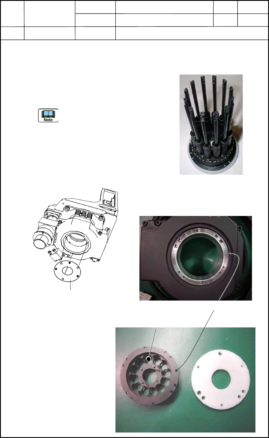
4.3 Attachment of Nozzle Shaft Assembly
4.3.1 Attachment of Assembly to DD Motor Side
(1) Attach the nozzle shaft assembly (Fig. E29) to
the DD motor side with three screws
(M1.6L5). (Fig. E30)
(a) Align the cutout of the positioning
pin (located at the bottom of the
DD motor) with the cutout of the
nozzle shaft assembly side (Figs.
E31 and E32) and insert the
assembly into the DD motor side.
(b) Do not leave any clearance at the
mating portion.
Fig. E29 Nozzle Shaft Assembly
Fig. E30 Attachment of Nozzle Shaft Assembly
Nozzle Shaft Assembly
Positioning Pin
Position of #1 Nozzle
Fig. E31 Bottom of DD Moto
r
Fig. E32 Nozzle Shaft Attachment Section
and Nozzle Holding Jig
0406-001
5-15
Device
Name
Chip Mounter
Block Name
Page No.
Unit Name
Revision
Model Item GXH-1
Chapter 5 Head Section
4. Replacement of Nozzle Shaft
Nozzle Shaft Assembly
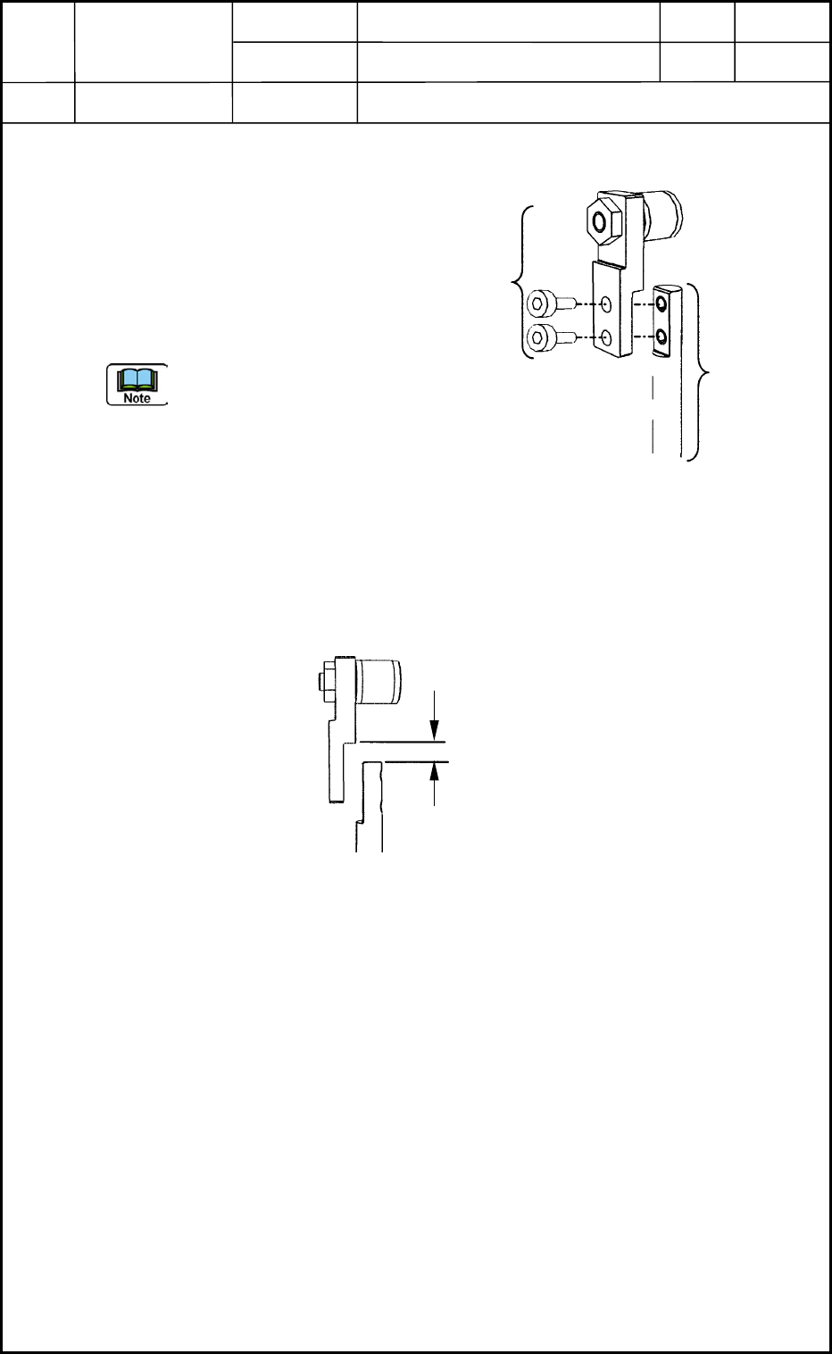
4.3.2 Assembly of Cam Follower Section
Assemble the cam follower section
(located at the upper area of the
nozzle shaft) to the nozzle shaft with
two bolts (M1.6L3). (Fig. E33)
Tightening Torque:
720 gf/cm
(Use Screw Lock 1401B.)
(a) Attach the nozzle
shaft and cam
follower vertically
without leaving any
clearance between
Face A of the cam
follower and Face B
of the nozzle shaft. (Fig. E34)
(b) In principle, the disassembled cam follower section and nozzle shaft must be
reassembled.
Fig. E34 Attachment of Cam Follower Section
A
B
0406-001
5-16
M1.6L3
Fig. E33 Assembly of Cam Follower Section
to Nozzle Shaft
Cam Follower
Section
Nozzle Shaft
Device
Name
Chip Mounter
Block Name
Page No.
Unit Name
Revision
Model Item GXH-1
Chapter 5 Head Section
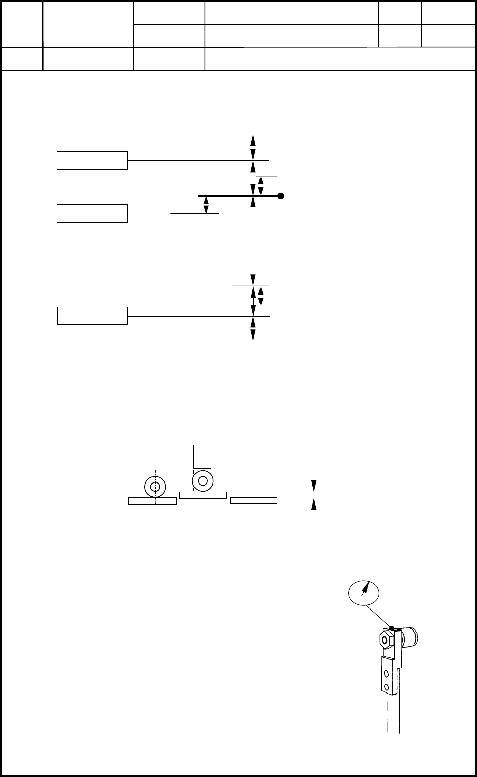
5. Location of Each Sensor
5.1 Location of NL-Axis Sensors and Stoppers
• NL-Axis Origin Position
(1) After the NL axis has been zeroed, check to see how the cam is shifted (transition)
before the NS axis is zeroed.
(2) After adjusting the NL-axis origin position as shown in Fig. E36, zero the NS axis.
Move the NS axis by -25°, -20°, 0°, 20°, and 25° and measure the amount of
transition (cam shift).
Specified Value: Loosen the coupling
of the NL axis and adjust the origin
position until the amount of transition
becomes "±0.01 mm or less".
B3105
B3102
B3104
(-) Limit Sensor
((-) Soft Limit)
(-) Mechanical Stopper
(+) Mechanical Stopper
(+) Limit Sensor
NL-Axis Basic Stroke
U/D Interlock
Photosensor
(mm)
19.0
0.3 to 0.4
0.5 ± 0.2
0.5
0.5
Fig. E35 Nozzle Level Axis
(0.2)
(0.2)
0.5
±
0.2
((+) Soft Limit)
NL-Axis Origin
Visual Check: Approx. 0.2 mm or less
Fig. E36 Cam Shift (Transition)
Fig. E37 Cam Shift (Transition)
0406-001
5-17