SM-131-006.pdf - 第119页
Device Name Chip Mounter Block Name Page No. Unit Name Revision Model Item GXH-1 Chapter 5 Head Section 5. Location of Each Sensor 5.2 Location of HL-Axis Sensors and Stoppers • HL-Axis Origin Position (Referential Value…
Device
Name
Chip Mounter
Block Name
Page No.
Unit Name
Revision
Model Item GXH-1
Chapter 5 Head Section
5. Location of Each Sensor
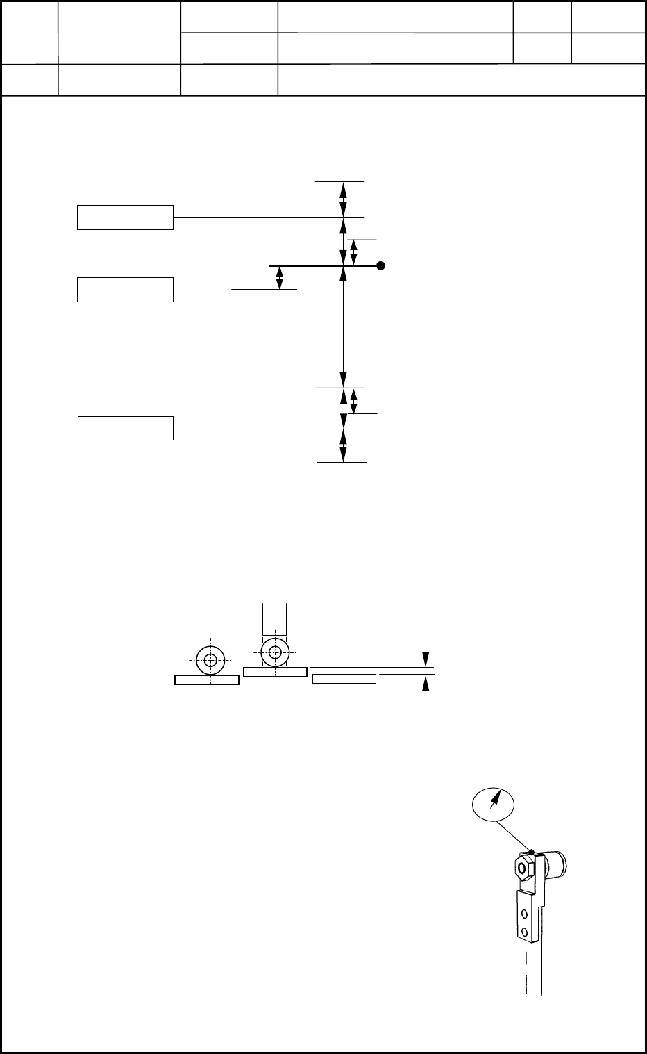
5.1 Location of NL-Axis Sensors and Stoppers
• NL-Axis Origin Position
(1) After the NL axis has been zeroed, check to see how the cam is shifted (transition)
before the NS axis is zeroed.
(2) After adjusting the NL-axis origin position as shown in Fig. E36, zero the NS axis.
Move the NS axis by -25°, -20°, 0°, 20°, and 25° and measure the amount of
transition (cam shift).
Specified Value: Loosen the coupling
of the NL axis and adjust the origin
position until the amount of transition
becomes "±0.01 mm or less".
B3105
B3102
B3104
(-) Limit Sensor
((-) Soft Limit)
(-) Mechanical Stopper
(+) Mechanical Stopper
(+) Limit Sensor
NL-Axis Basic Stroke
U/D Interlock
Photosensor
(mm)
19.0
0.3 to 0.4
0.5 ± 0.2
0.5
0.5
Fig. E35 Nozzle Level Axis
(0.2)
(0.2)
0.5
±
0.2
((+) Soft Limit)
NL-Axis Origin
Visual Check: Approx. 0.2 mm or less
Fig. E36 Cam Shift (Transition)
Fig. E37 Cam Shift (Transition)
0406-001
5-17
Device
Name
Chip Mounter
Block Name
Page No.
Unit Name
Revision
Model ItemGXH-1
Chapter 5 Head Section
5. Location of Each Sensor
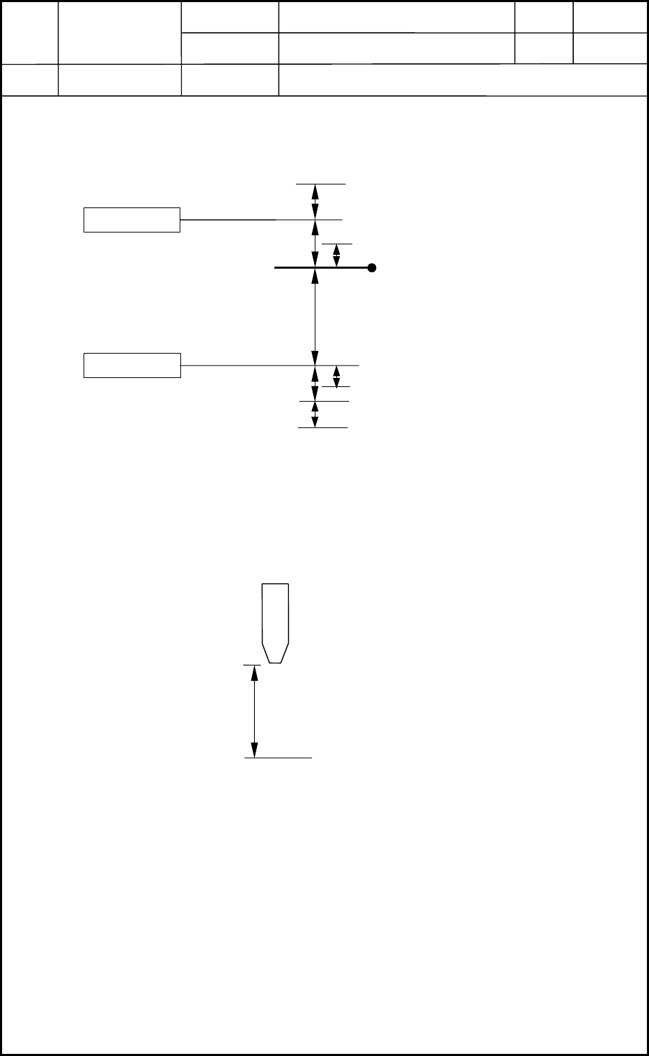
5.2 Location of HL-Axis Sensors and Stoppers
• HL-Axis Origin Position (Referential Value)
(1) Confirm that the NL-axis origin adjustment is already finished.
(2) Loosen the HL-axis coupling and adjust the stoke so that it can be "32±0.05 mm" as
shown below after the HL axis is zeroed.
Fig. E38 Head Level Axis
Photosensor
B3103
B3106
(-) Limit Sensor
(-) Mechanical Stopper
(+) Mechanical Stopper
(+) Limit Sensor
HL-Axis Origin
(mm)
24.0
1 ± 0.1
1
(0.5)
((-) Soft Limit)
((+) Soft Limit)
(0.5)
1 ± 0.2
1
HL-Axis Basic Stroke
Master Nozzle
(NL- and HL-Axis Origin Position)
Fig. E39 HL-Axis Origin Position
Design Value of Stroke: 32 mm
PCB Upper Surface Reference Point
0406-001
5-18
Device
Name
Chip Mounter
Block Name
Page No.
Unit Name
Revision
Model ItemGXH-1
Chapter 5 Head Section
5. Location of Each Sensor
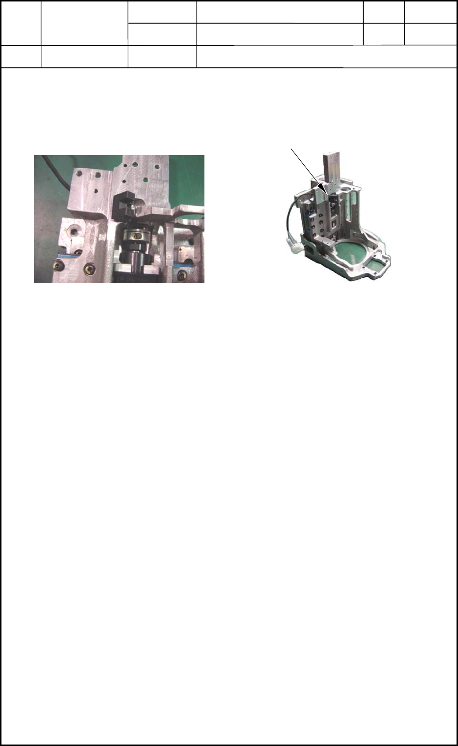
5.3 Nozzle Position Selection Detection Sensor
See Figs. E40 and E41.
Fig. E40 Nozzle Position Selection
Detection Sensor
Fig. E41 Location of Nozzle Position
Selection Detection Sensor
Nozzle Position Selection Detection Sensor
0406-001
5-19