SM-131-006.pdf - 第132页
Device Name Chip Mounter Block Name Page No. Unit Name Revision Model Item GXH -1 Chapter 5 Head Section 7. MSB W hole Cleaning and Lubricat ion Procedures (13) After wiping out the old g rease of th e nozzle holder O- r…
Device
Name
Chip Mounter
Block Name
Page No.
Unit Name
Revision
Model Item GXH-1
Chapter 5 Head Section
7. MSB Whole Cleaning and Lubrication Procedures
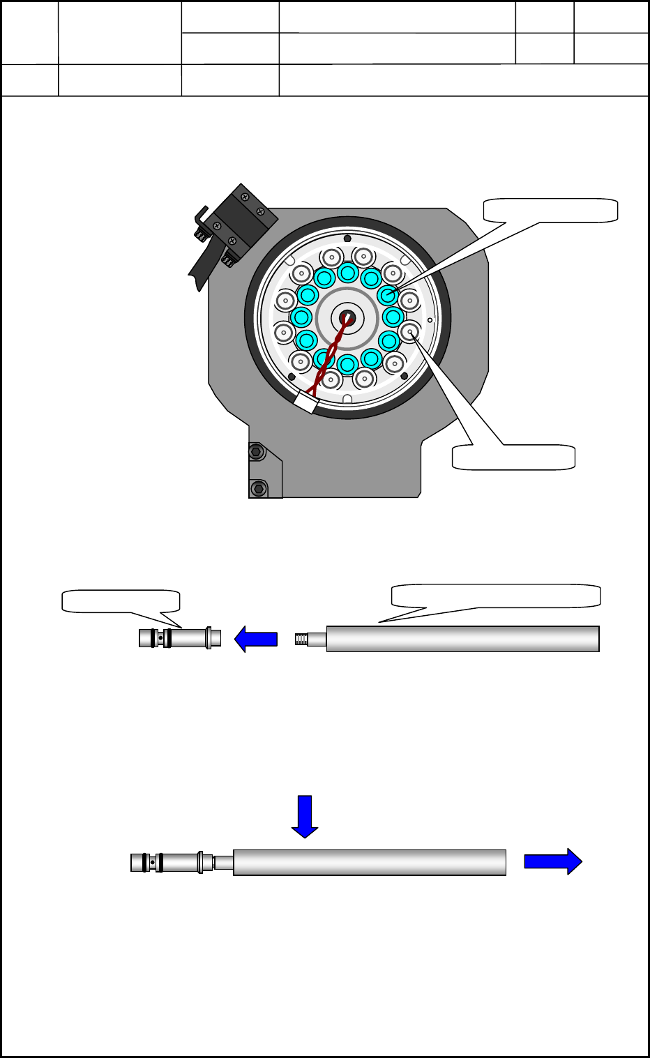
(12) Remove 12 nozzle holders from the DD motor (upper rotor) with a nozzle holder
inserting Jig.
* This nozzle holder inserting jig has become a screw type so, tuck the nozzle holder
inserting jigs in the nozzle holders for each 10-sections and pull out the nozzle
holders together with the jigs.
Fig. E59
Nozzle Holder
Vacuum Valve
View of Head Bottom Surface
Nozzle Holder Inserting Jig
Nozzle Holder
0605-001
5-30
Device
Name
Chip Mounter
Block Name
Page No.
Unit Name
Revision
Model Item GXH-1
Chapter 5 Head Section
7. MSB Whole Cleaning and Lubrication Procedures
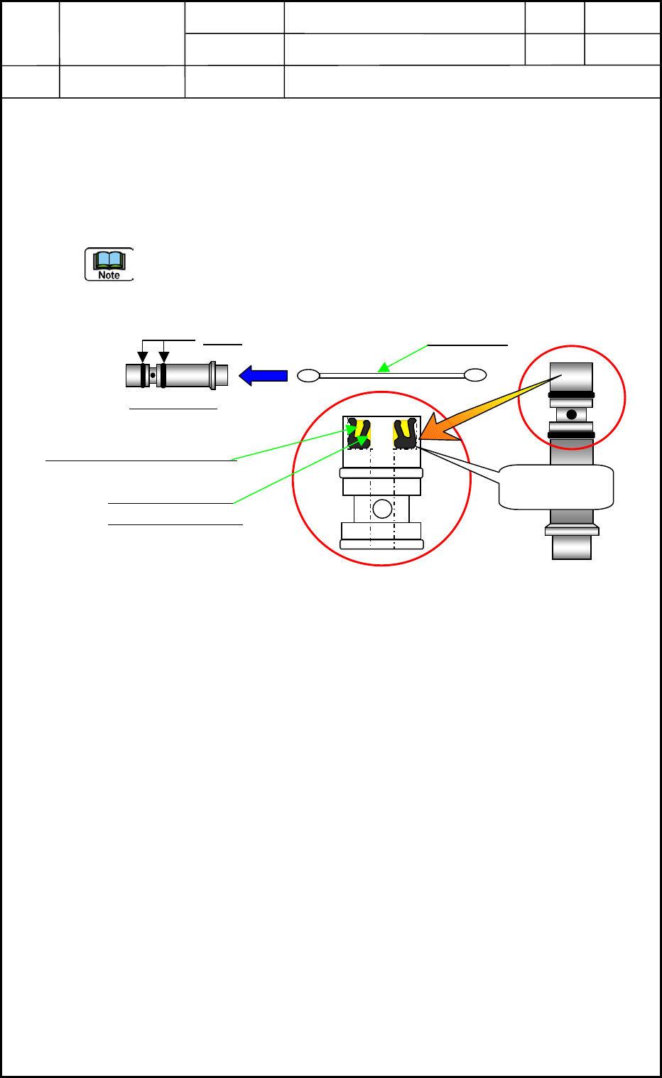
(13) After wiping out the old grease of the nozzle holder O-ring section, apply a small
amount of new grease to the outer circumference of the O-ring section thinly. Wipe off
the soil or etc. of the V-packing <Fig. E60> and bridge the V-groove section with grease,
as well as applying grease thinly to the V-packing shaft washer.
Clean up the nozzle holder inside with a cotton swab dipped in alcohol.
Face the groove side of the V-packing up when the V-packing is reset to the former
position as it
was.
Fig. E60
O-ring
Cotton Swab
Nozzle Holder
Bridge the groove with grease.
Apply grease to the
shaft washer surface.
V-packing
Part No.-S29
0605-001
5-31
Device
Name
Chip Mounter
Block Name
Page No.
Unit Name
Revision
Model Item GXH-1
Chapter 5 Head Section
7. MSB Whole Cleaning and Lubrication Procedures
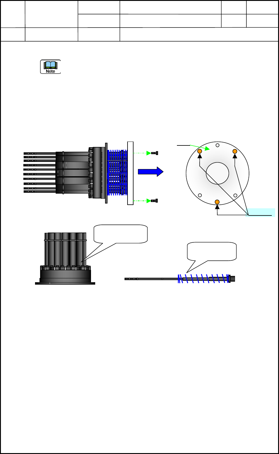
(14) Detach the head section attaching jig from the nozzle shaft assy. <Fig. E61>
- Please support the jig by hand in removing the bolts (M1.6×L4) because springs are
set for the each nozzle shaft in the nozzle shaft assy. If an operator does not support
the jig, the springs will jump out as soon as detaching the jig. And, put marks on the
jig like Fig. E61 to distinguish the attaching position. This mark will help your
operations later.
- Be careful do not add force to the shaft when you support the shaft section by hand.
And check that the serial No.’s are marked on the shaft. If not, manage the shafts
positions to reset to the outer cover.
Fig. E61
Mark
Lower Rotor and
Outer Cover
Nozzle Shaft
and Spring
M1.6×L4
No.1
0605-001
5-32