SM-131-006.pdf - 第149页
Device Name Chip Mounter Block Name Page No. Unit Name Revision Model Item GXH -1 Chapter 5 Head Section 7. MSB W hole Cleaning and Lubricat ion Procedures Recheck af ter operations are com pleted. Fig. E85 Wi t h i n ± …
Device
Name
Chip Mounter
Block Name
Page No.
Unit Name
Revision
Model Item GXH-1
Chapter 5 Head Section
7. MSB Whole Cleaning and Lubrication Procedures
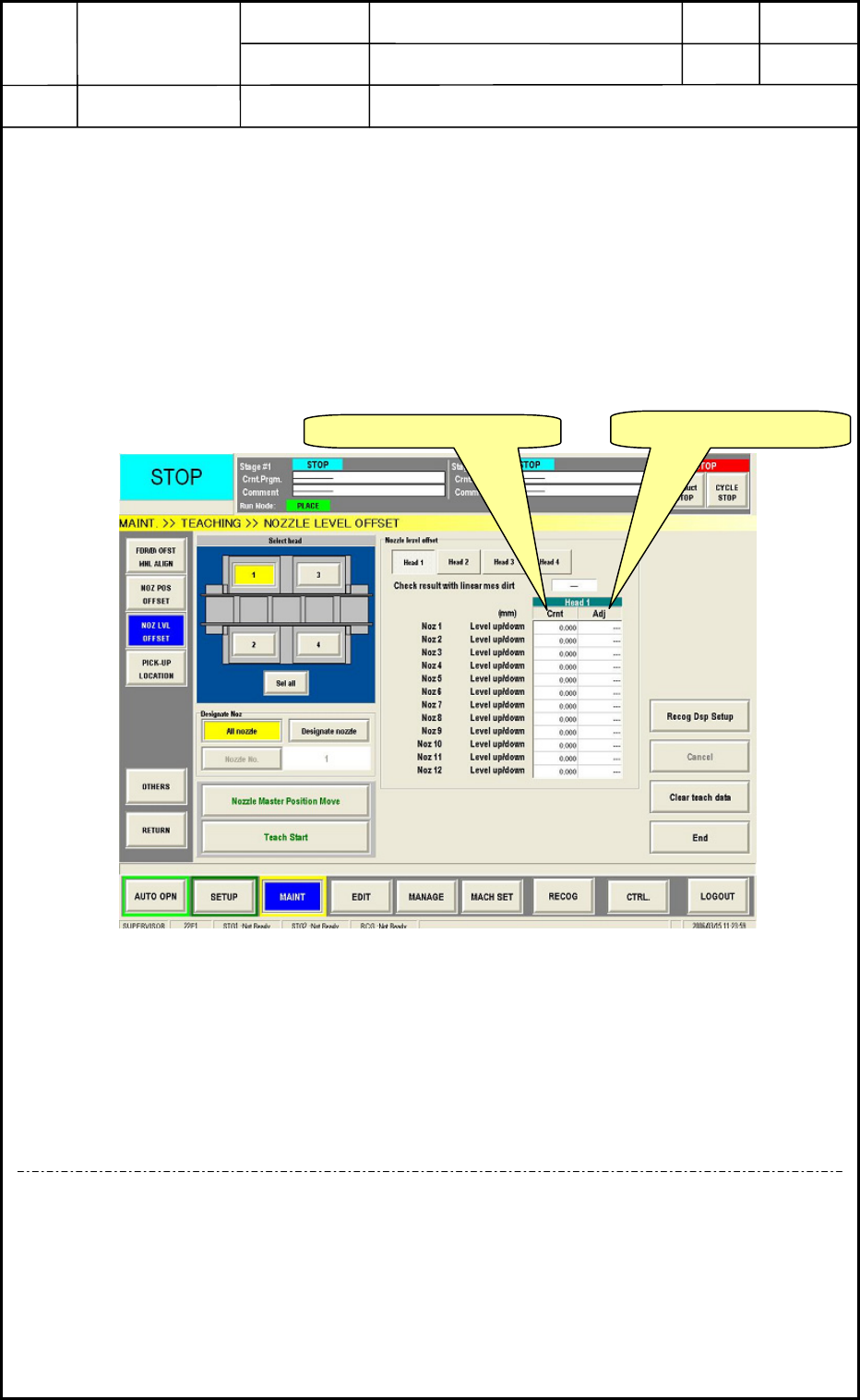
• At the [SETUP] => [NOZZLE] tab sheet, perform the nozzle change. The heads
cleaned this time will go taking the nozzles used before in the nozzle level teaching
operation. In this case, the order should be the same as before. (No special operation
is required to make the same condition as before.)
• Perform the nozzle level offset teaching against the heads cleaned and supplied this
time.
• Compare the difference of data between the “after lubrication” and the “before
lubrication” with the teaching result and the difference should be ±0.01mm against
the all nozzles.<Fig. E84>
Fig. E84
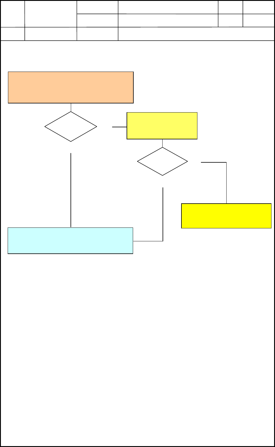
• When the difference is within ±0.01mm, perform teaching operation for others:
nozzle position offset.
• After teaching operation, reset the “Disable” to the “Enable”. Then, this all operations
are completed.
<In case of out of range>
If the difference is not within ±0.01mm, recheck the linear measure sensor attaching direction
and position, soil, damage or etc. otherwise, the bottom rotor section and linear measure
sensor attaching section have trashes and soils or the screw lock (Three Bond 1401B) remains.
Nevertheless, when the problem can not be improved, contact nearest service personnel in our
company.
Before Lubrication data
After Lubrication data
0605-001
5-47
Device
Name
Chip Mounter
Block Name
Page No.
Unit Name
Revision
Model Item GXH-1
Chapter 5 Head Section
7. MSB Whole Cleaning and Lubrication Procedures
Recheck after operations are completed.
Fig. E85
Within
±0.01 mm
Yes
No
Teaching results of the nozzle level
teaching between “after lubrication” data
and “before lubrication” data.
Perform the nozzle position offset
teaching and complete this operation.
Recheck after
cleaning of the linear
measure sensor.
Yes
No
Please contact nearest
service
p
ersonnel.
Within
±0.01 mm
0605-001
5-48

Chapter 6
Backup Base Section
This chapter describes the backup base section.
• Replacement of Backup Base Motor
• Replacement of Backup Base Servoamplifier
• Backup Base Sensor Position
• Backup Base Offsets
0406-001 6-A