SM-131-006.pdf - 第162页
Device Name Chip Mounter Block Name Page No. Unit Name Revision Model Item GXH-1 Chapter 7 Transfer Section 1. Replacement of Transfer Motors • Before the maintenance work, be sure to shut down the power supply to the ma…

0406-001 7-B
Device
Name
Chip Mounter
Block Name
Page No.
Unit Name
Revision
Model ItemGXH-1
Chapter 7 Transfer Section
1. Replacement of Transfer Motors
• Before the maintenance work, be sure to shut down the power supply to the
machine and make preparations such as detachment of the cover, etc.
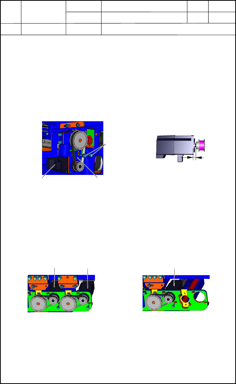
1.1 Replacement of Transfer Motors in NR and NL Sections
(1) Pull out the connector of the motor, loosen two anchor bolts (shown in Fig. G1), and
detach the motor.
(2) Attach the pulley of the detached motor to the new motor, keeping the distance shown
in Fig. G2 and mount the new motor on the main body.
(3) Adjust the tension of the belt by moving the motor mounting plate.
Refer to "3. Set Values for Various Belt Tensions" in Chapter 3 for details.
1.2 Replacement of Transfer Motors in NA, NB, and NC Sections
(1) Remove the two bolts for each motor in the NA, NB, and NC sections and detach the
motors from the main body.
(2) Attach the pulley of the detached motor to the new motor, keeping the distance shown
in Fig. G2 and mount the new motor on the main body.
(3) Adjust the tension of the belt by moving the motor.
Refer to "3. Set Values for Various Belt Tensions" in Chapter 3 for details.
5.0±0.2 mm
Fi
g
. G2 Dimension
Fig. G1 Transfer Motor Section
Plate
Motor
Bolts
Motor in NB Section
Motor in NA Section
Fig. G3 NA and NB Sections
Fig. G4 NC Section
Motor in NC Section
0406-001
7-1
Device
Name
Chip Mounter
Block Name
Page No.
Unit Name
Revision
Model ItemGXH-1
Chapter 7 Transfer Section
1. Replacement of Transfer Motors
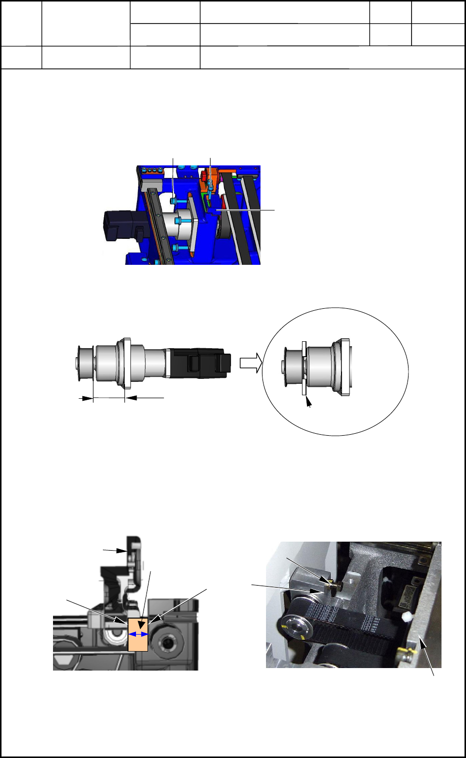
1.3 Replacement of Pullover Motors in NR and NL Sections
(1) Pull out the connector of the motor, loosen Bolt A (shown in Fig. G5), move Block A,
and loosen the belt.
(2) Remove Bolt B (shown in Fig. G5) and detach the motor unit.
(3) Attach the mechanical lock of the detached motor to the new motor as shown in
Fig. G6 and mount the new motor on the main body.
(4) Adjust the tension of the belt by moving Block A in Fig. G5. (Use a vice.)
Refer to "3. Set Values for Various Belt Tensions" in Chapter 3 for details.
(5) Determine the position of the chute as shown in Fig. G7 while the motor is set in the
"Phase C" mode (Phase C Detection Jig Used) and tighten the mechanical lock
securely.
Tightening Torque: 392 N (40 kgf/cm)
(6) Adjust the sensor so that the limit sensor of the chute is set in the "E/NR" (Light
Emitted and Not Received) mode at the same position as in Fig. G7. Now, the
replacement work is completed.
Block A
Bolt B
Bolt A
Fig. G5 Pullover Motor
37.8 mm
Thickness Gauge (3 mm)
Fig. G6 Mechanical Lock
Block Gauge
13.5 mm
Fig. G7 Setting of Reference Position for Chute
Stopper Mounting Face
Stopper Working Face
Chute
Chute
Stopper
Fig. G8
0406-001
7-2