SM-131-006.pdf - 第166页
Device Name Chip Mounter Block Name Page No. Unit Name Revision Model Item GXH-1 2. Replacement of Transfer Belts Chapter 7 Transfer Section (5) Follow the reverse order of detachment to reassemble each part. When each p…
Device
Name
Chip Mounter
Block Name
Page No.
Unit Name
Revision
Model ItemGXH-1
2. Replacement of Transfer Belts
Chapter 7 Transfer Section
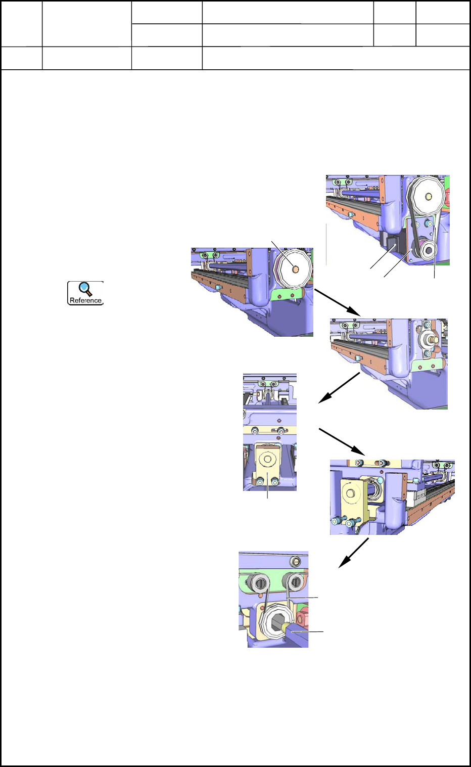
2.1 Replacement of Transfer Belts
• Five sets of transfer belts are used in the NR, NL, NA, NB, and NC sections.
Basically, the same procedure should be followed to replace each belt with a new
one.
(1) Detach the transfer motor,
the plate, and the belt
shown in Fig. G13. Fig.
G14 shows the pulley of
the rod without the
transfer motor, the plate,
and the belt.
Refer to "1.
Replacement of
Transfer Motors"
for details.
(2) Detach the pulley of the
rod shown in Fig. G14.
Fig. G15 shows the
condition without the
pulley.
To detach the pulley,
loosen the two setscrews
and pull it out.
(3) Loosen the bolts of Block
A (shown in Fig. G16)
located on the opposite
side and pull out Block A
and the rod as shown in
Fig. G17.
(4) Replace the belt with a
new one under the
condition shown in Fig.
G18.
Fig. G18
Fig. G13
Fig. G14
Fig. G15
Fig. G16
Fig. G17
Motor
Belt
Plate
Pulley of Rod
Block A
Rod
Transfer Belt
0406-001
7-4

Device
Name
Chip Mounter
Block Name
Page No.
Unit Name
Revision
Model ItemGXH-1
2. Replacement of Transfer Belts
Chapter 7 Transfer Section
(5) Follow the reverse order of detachment to reassemble each part.
When each parts is reassembled, check the set values in Table G1.
Table G1
Spots Set Values
Clearance between Rod and Pulley Feel the clearance by hand.
Rotational Torque of Rod 3.9 N (0.40 kgf/cm) or less
Tension of Transfer Belt Refer to "3. Set Values for Various Belt Tensions"
in Chapter 3 for details.
Tension of Transfer Motor Belt Refer to "3. Set Values for Various Belt Tensions"
in Chapter 3 for details.
0406-001
7-5
Device
Name
Chip Mounter
Block Name
Page No.
Unit Name
Revision
Model ItemGXH-1
Chapter 7 Transfer Section
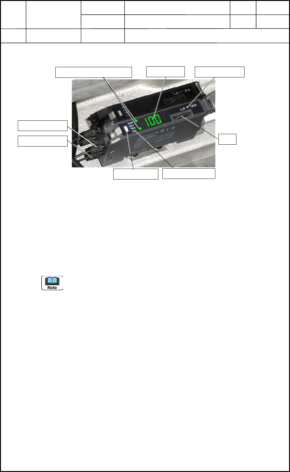
3. Setting of PCB Detection Sensor Amplifiers in NA and NC Sections
3.1 Name of Each Section in PCB Detection Sensor Amplifier
3.2 Basic Operations of PCB Detection Sensor Amplifier
(1) When the power is supplied, the amplifier is set in the "RUN" mode and the "RUN"
indicator lamp illuminates.
(2) When the D-SW is pressed, the "RUN" indicator lamp flickers, indicating that the
mode selection is set ready.
Rotate the D-SW to change the mode.
(3) When the D-SW is pressed at the point where the desired mode indicator lamp
flickers, the amplifier is set in the selected mode.
When the mode indicator lamp is kept intact (flickering) for 60 seconds, the
amplifier is reset to the "RUN" mode.
3.3 Mode Types
RUN Mode : Normal Detection Mode
SET Mode : In this mode, the detection function can be set and the sensitivity can be
adjusted.
TMR Mode : In this mode, the timer function can be set and the time of the timer can be
adjusted.
ADJ Mode : In this mode, the threshold value can be changed. When the maximum
sensitivity is set (factory-adjusted at shipment), the amplifier cannot be set
in the "ADJ" mode.
Light Receiving Side
Fi
g
. G19 PCB Detection Sensor Amplifier
Light Emitting Side
OPN Mode Lamp
Auxiliary Mode Indicator Lamps
Digital Display
L-ON/D-ON Switch
D-SW
Mode Indicator Lamp
0406-001
7-6