SM-131-006.pdf - 第169页
Device Name Chip Mounter Block Name Page No. Unit Name Revision Model Item GXH-1 Chapter 7 Transfer Section 3. Setting of PCB Detection Sensor Amplifiers in NA and NC Sections 3.6 Setting of Each Item (1) Set the L-ON/D-…
Device
Name
Chip Mounter
Block Name
Page No.
Unit Name
Revision
Model ItemGXH-1
Chapter 7 Transfer Section
3. Setting of PCB Detection Sensor Amplifiers in NA and NC Sections
3.4 Table of Each Item for Settings
Table G2
Item Settings
L-ON/D-ON Switch D-ON
Received Light Level Indicator AA (Standard)
Detection Function HP (Super-Long Distance)
Sensitivity Setting PH (Percent Sensitivity Setting)
Timer Function Setting t0 (Momentary)
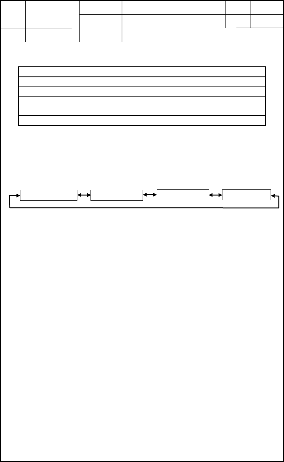
3.5 Confirmation of Settings for Each Item
Every time the D-SW is rotated with the amplifier in the "RUN" mode, the digital indicator
indicates the set condition of the following items according to the rotation.
Detection FunctionReceived Light Level
Timer Function Sensitivity Setting
0406-001
7-7
Device
Name
Chip Mounter
Block Name
Page No.
Unit Name
Revision
Model ItemGXH-1
Chapter 7 Transfer Section
3. Setting of PCB Detection Sensor Amplifiers in NA and NC Sections
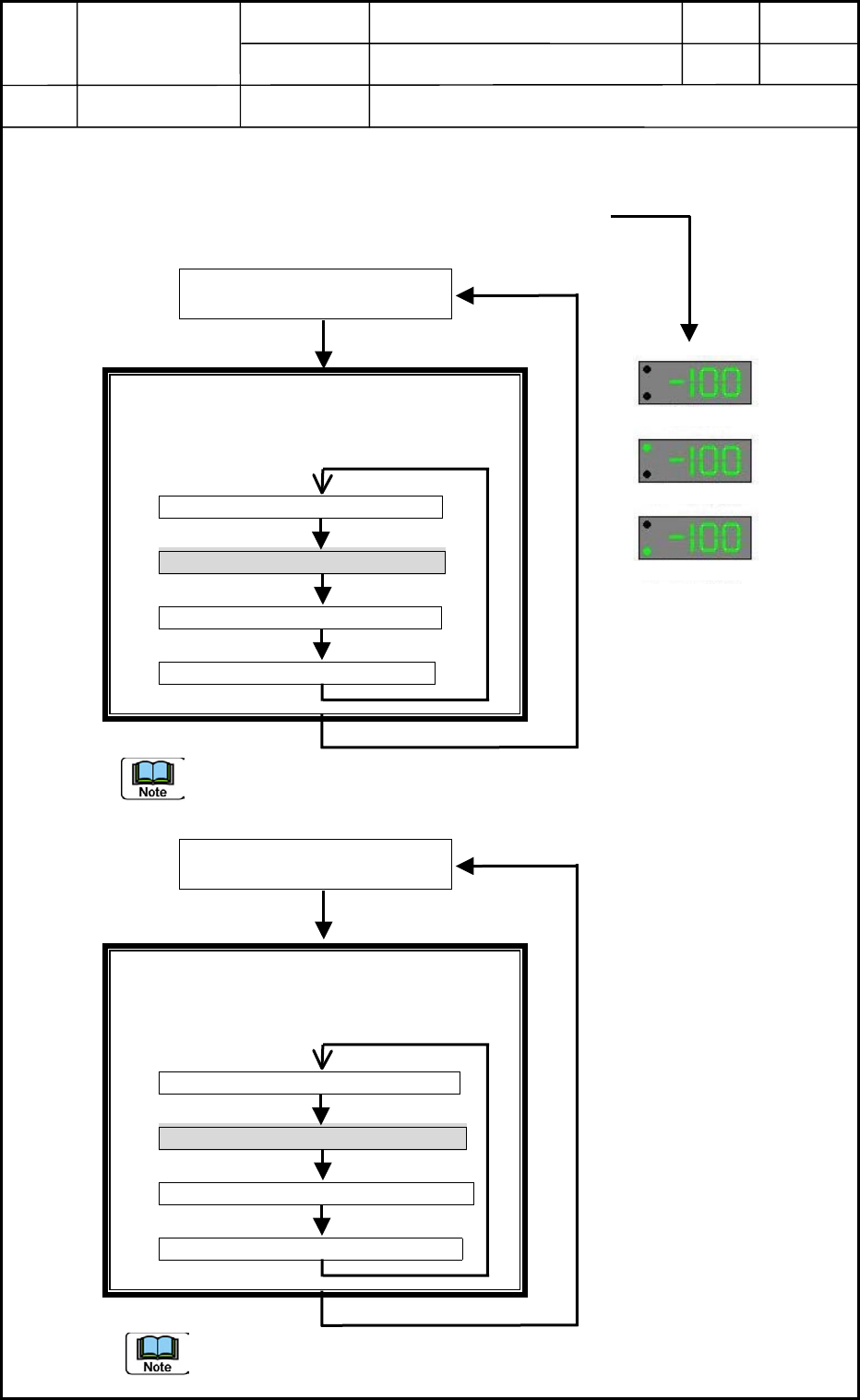
3.6 Setting of Each Item
(1) Set the L-ON/D-ON switch to "D-ON".
(2) Check the level of the received light.
(Check only if "AA (Standard)" is displayed or not.)
Mode Indicator Lamps: All OFF
Auxiliary Mode Indicator Lamps: ON
When the D-SW is rotated in this mode, the
indication changes as follows.
Peak Indication (PP Flickering)
Standard Indication (AA Flickering)
Bottom Indication (bb Flickering)
Cancel (-- Flickering)
Press the D-SW.
To interrupt the setting change, select "Cancel".
(3) Set the detection function. (Set to HP "Super-Long Distance".)
Mode Indication: "SET" ON
Auxiliary Mode Indicator Lamps: ON
When the D-SW is rotated in this mode, the
indication changes as follows.
Standard (nL Flickering)
Super-Long Distance (HP Flickering)
High-Speed Response (HS Flickering)
Cancel (-- Flickering)
Press the D-SW.
(a) When the detection function is selected, the sensitivity setting is reset.
(b) To interrupt the setting change, select "Cancel".
"RUN" Lamp Flickering in
"Mode Selection" Mode
Hold down the D-SW for
more than 3 seconds.
Standard Indication
Standard IndicationPeak Indication
Bottom Indication
"SET" Flickering in "Mode
Selection" Mode
Hold down the D-SW for
more than 3 seconds.
0406-001
7-8
Device
Name
Chip Mounter
Block Name
Page No.
Unit Name
Revision
Model ItemGXH-1
Chapter 7 Transfer Section
3. Setting of PCB Detection Sensor Amplifiers in NA and NC Sections
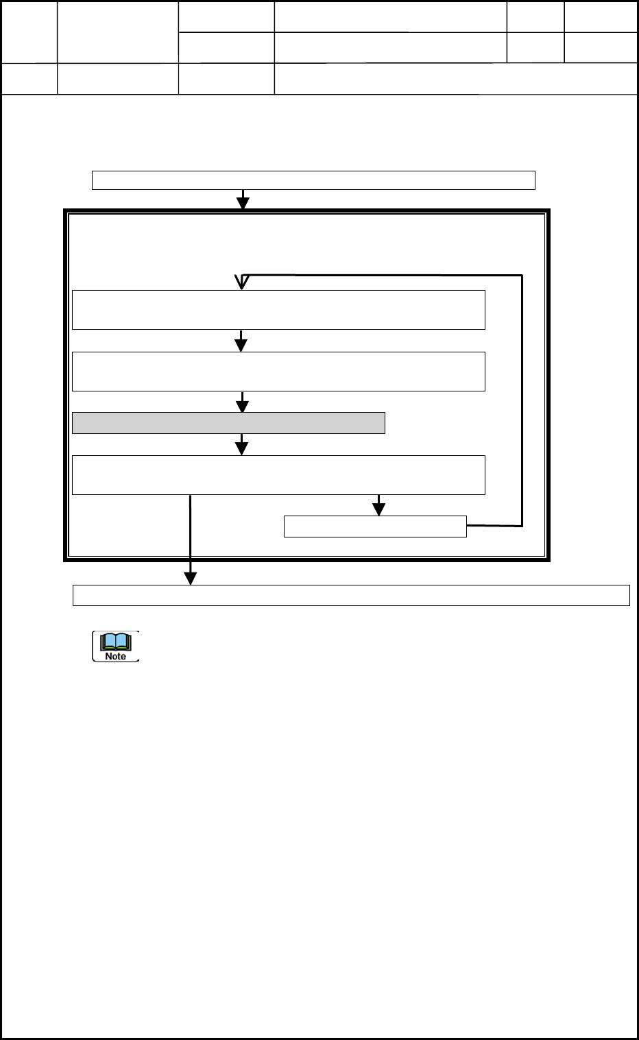
(4) Set the sensitivity.
(Set to "Percent Sensitivity Setting (PH)". Set Level: 50%)
Mode Indication: "SET" ON
Auxiliary Mode Indicator Lamps: OFF
When the D-SW is rotated in this mode, the indication changes as follows.
Press the D-SW.
The settings may become unavailable, depending on how the light is received
during the setting operations. In this case, slightly change the distance of the fiber
for the detection and perform the settings again.
Press the D-SW.
After the detection function is selected, the following condition is set.
Attach the fiber in the "100%" mode desired as a reference.
(PH Flickering)
Set Operation Level Indication "50 to 150%" (the value relative
to one regarded as a reference in the previous operation)
Rotate the D-SW.
Adjustment to Desired Level (50 to 150%):
Press the D-SW.
When the difference in the levels is insufficient, "LE" is turned
ON. When the setting is impossible, "dE" is turned ON.
Rotate the D-SW.
Cancel (-- Flickering)
Press the D-SW.
Press the D-SW.
After the settings are completed, the amplifier is reset to the "Mode Selection" mode.
0406-001
7-9