SM-131-006.pdf - 第176页
Device Name Chip Mounter Block Name Page No. Unit Name Revision Model Item GXH -1 Chapter 8 Com ponent Supply Section 1. Assembly of Feeder Positioning Section 1.3 Assembly of Gear Section (1) Attach the gear unit to Sec…
Device
Name
Chip Mounter
Block Name
Page No.
Unit Name
Revision
Model Item GXH-1
Chapter 8 Component Supply Section
1. Assembly of Feeder Positioning Section
(2) Both sides of the center stand on the frame should be regarded as reference ones.
Push the unit (X direction) on the center stand side against the stepped section.
Push the unit (Y direction) against the positioning pins on the frame and fix it securely.
(M10L40 SW, FW × 2)
As for the unit on the opposite side, push it (only Y direction) for temporary attachment.
(3) Temporarily attach the assembled gear sections to Unit Bases A and B.
(M8L20 SW, FW)
(4) Mount the unit positioning jig and adjust the X direction of the unit on the opposite side
of the center stand so that the jig can be detached and re-attached smoothly.
Adjust the X direction of the unit positioning jig at the center of the slot section shown
in Fig. H6. (As for the Y direction, push it against the pin.)
1.2 Pneumatic Piping
1.2.1 Adjustment
(1) Rotate the speed controller for elevation
one-and-a-half turns from the fully closed
condition and rotate the cushion two-and-
a-half turns backward from the fully
closed condition. After that, lock them.
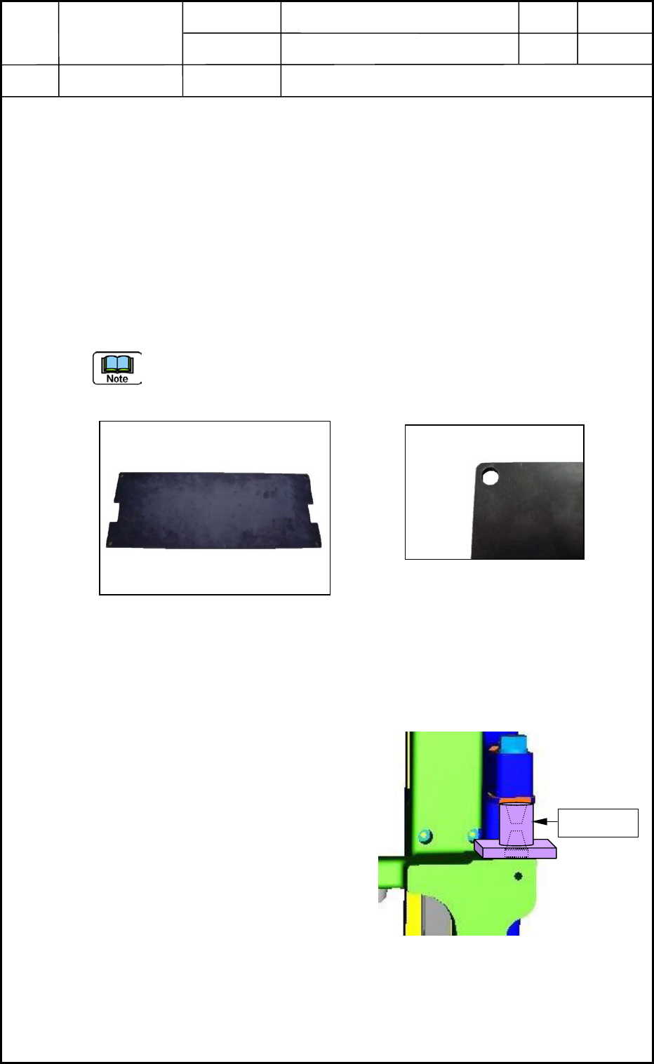
(2) Attach the holding jig to the positioning
section and make the cylinder ascend.
Make sure that the mounting jig can be
pinched.
(3) Check the movement of the cylinder
through the manual operation of the valve.
Fig. H5 Unit Positioning Jig
Fig. H6 Slot Section of Unit Positioning Jig
Holding Jig
Fig. H7 Positioning of X Direction
0406-001
8-2
Device
Name
Chip Mounter
Block Name
Page No.
Unit Name
Revision
Model Item GXH-1
Chapter 8 Component Supply Section
1. Assembly of Feeder Positioning Section
1.3 Assembly of Gear Section
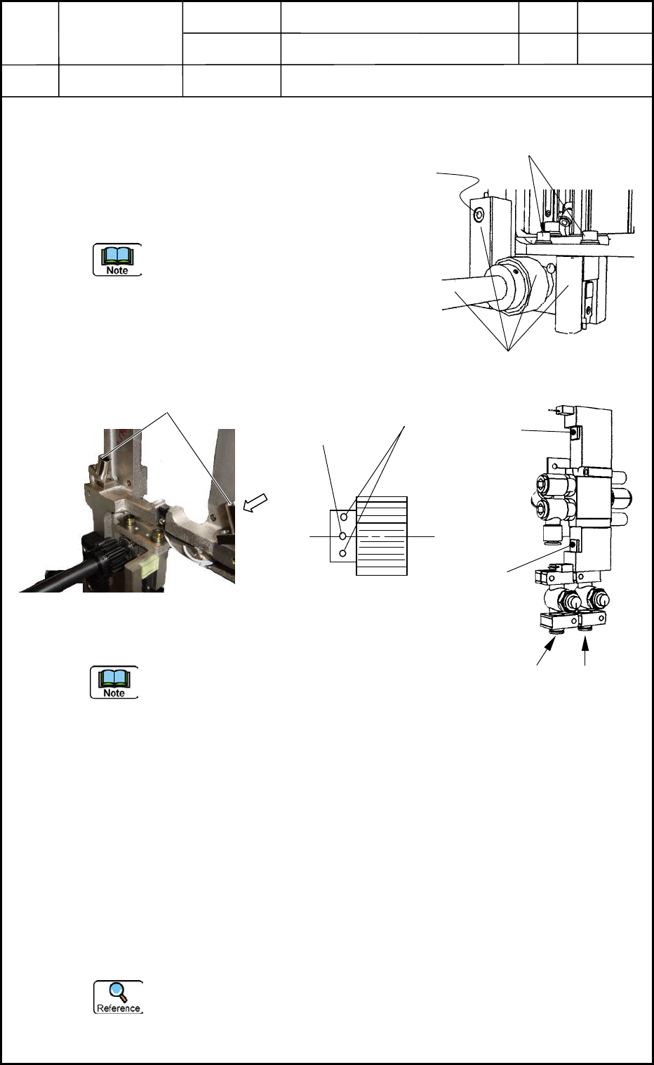
(1) Attach the gear unit to Sections A and B.
Confirm that the two setbolts (M8L30) on the rack
side (shown in Figs. H1 and H2) are loosened. (Use
of Screw Lock 1344)
Fix the gear unit by pushing it against the press-
fit pins (two pins in X direction and a pin in Y
direction) in Section A.
Also, push the gear unit against the press-fit pins
(two pins in Y direction) in Section B and fix the
X direction at the place where there is no play of
the shaft bearing.
Fig. H8 shows the direction of the gear at the
ascending of the positioning cylinder.
(2) Move up the positioning cylinder.
Be sure to slowly operate it.
(3) Adjust the play of the gear for "0.13 to 0.16 mm" at the ascending position of the
positioning cylinder (right side) in Fig. H1.
Apply a dial gauge as shown in Figs. H1 and H3 and make an adjustment (by tightening
M8L30) until the deflection becomes "0" at the ascending/descending position of the
positioning cylinder (the back of the rack).
After the adjustment, re-check the amount of play for the gear.
(4) Perform the same adjustment of the gear on the left side (Fig. H2).
Insert the setbolts into both gears to fix the shafts.
After the positional adjustment of the rack and gears, make holes at the pin hole position
with an electric drill and press-fit the spring pins (φ4L40).
Drill Diameter for Prepared Holes: φ4.0 to φ4.1 mm)
0406-001
8-3
C
Fig. H8 Jig Required at Upward
Movement of Positioning Cylinder
Jig
Ascent
Descent
Descent Ascent
Fig. H10 Cylinder Upward/
Downward Movement
View C (Direction of Gear)
Setbolts
Pin Hole
Fig. H9 Gear Unit
(M8L20 SW, FW)
Device
Name
Chip Mounter
Block Name
Page No.
Unit Name
Revision
Model ItemGXH-1
Chapter 8 Component Supply
2. Replacement of Cylinder and Valve for Feeder Clamping
2.1 Detachment of Cylinder & Valve for Feeder Clamping
(1) Pull out the cart from the machine.
Refer to the instruction manual for how to
pull out the cart.
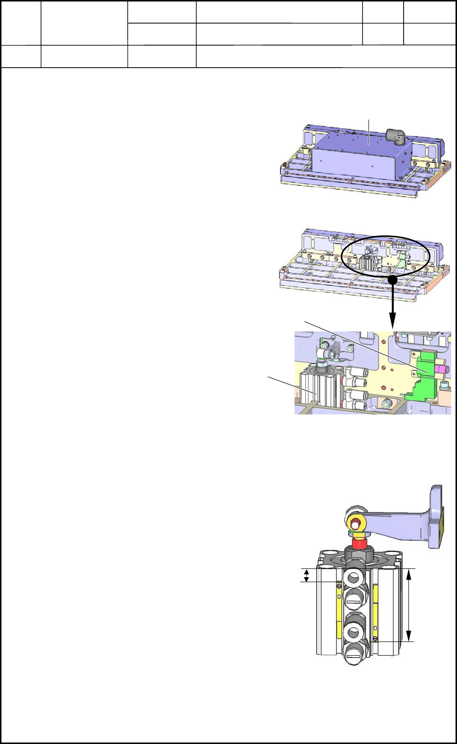
(2) Place the feeder base on the work bench as
shown in Fig. H13.
(3) Open the electrical box to expose the
contents as shown in Fig. H14.
(4) The cylinder and valve become visible as
shown in Fig. H15. Pull out the connector
and the hose from them and detach the
main body.
2.2 Attachment of Cylinder & Valve for Feeder Clamping
(1) Attach the proximity sensor of the cylinder
as shown in Fig. H16.
(2) Follow the reverse order of detachment to
attach the cylinder and the valve.
0406-001
8-4
Fig. H13
Electrical Box
Fig. H14
Valve
Fig. H15 Magnified View
Cylinder
18.0±0.5 mm
34.0±0.5 mm
Fig. H16