SM-131-006.pdf - 第189页
Device Name Chip Mounter Block Name Page No. Unit Name Revision Model Item GXH-1 Chapter 9 Cutter Section 3. Replacement of Cutter Axis Servomotor Amplifiers 3.3 Setting of Cutter Axis Servomotor Amplifier 3.4 Attachment…
Device
Name
Chip Mounter
Block Name
Page No.
Unit Name
Revision
Model ItemGXH-1
Chapter 9 Cutter Section
3. Replacement of Cutter Axis Servomotor Amplifiers
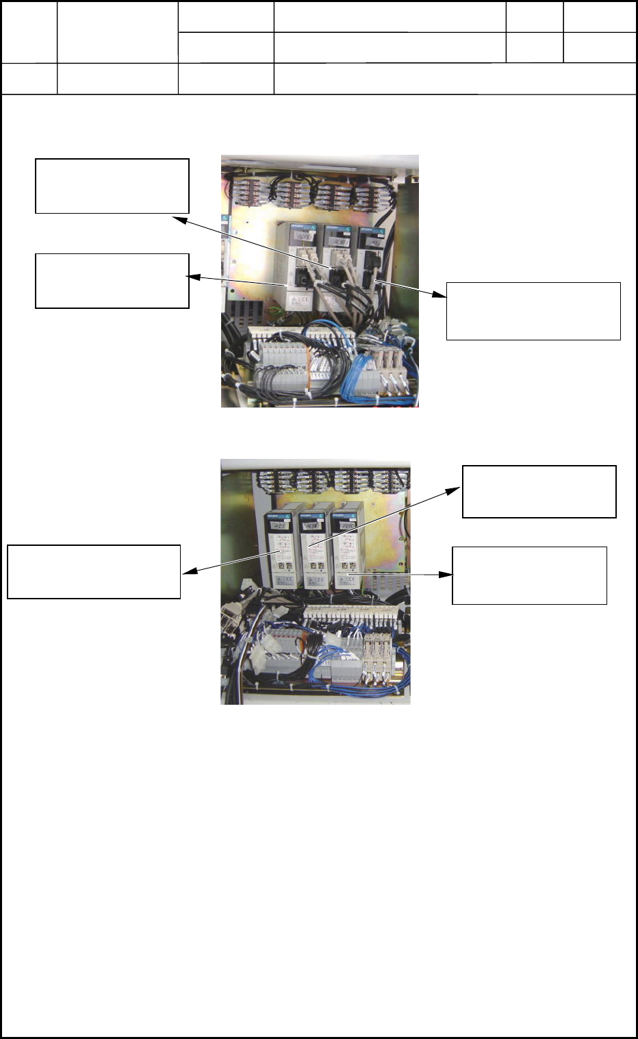
3.1 Location of Cutter Axis Servomotor Amplifiers (Drivers)
3.2 Detachment of Cutter Axis Servomotor Amplifier
(1) Disconnect Connectors CN1A, CN1B, CN2, and CN3 located just before the amplifier.
(2) Disconnect the power lines located under the amplifier.
Supply 200 V AC : L1, L2, and L3
Control 200 V AC : L11 and L21
Motor : U, V, W, and PE
(3) Detach the amplifier from the panel. The amplifier is fastened with screws.
0406-001
9-3
Cutter Axis in Section A
(A63)
Cutter Axis in Section B
(A63)
Backup Axis in Section NA
(A53)
Fig. I6 Bottom 1 Side of Main Machine (Block BA)
Cutter Axis in Section D
(A63)
Cutter Axis in Section
C
Backup Axis in Section NC
(A53)
Fig. I7 Bottom 3 Side of Main Machine (Block BC)
Device
Name
Chip Mounter
Block Name
Page No.
Unit Name
Revision
Model ItemGXH-1
Chapter 9 Cutter Section
3. Replacement of Cutter Axis Servomotor Amplifiers
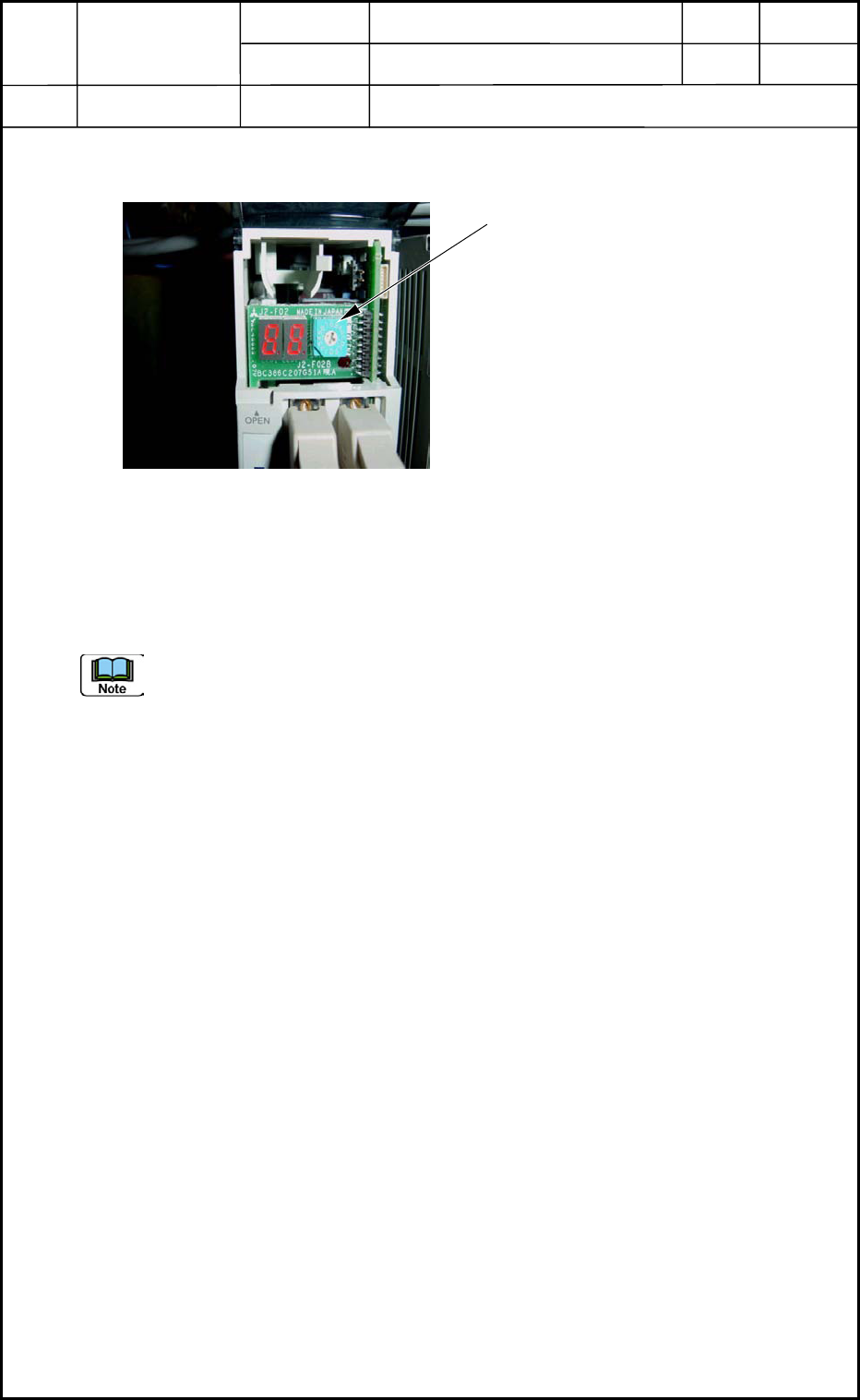
3.3 Setting of Cutter Axis Servomotor Amplifier
3.4 Attachment of Cutter Axis Servomotor Amplifier
Refer to "2. Replacement of Cutter Axis Motor" and "3. Replacement of Cutter Axis
Servomotor Amplifiers" for how to attach the cutter axis servomotor amplifier.
Note the connection of the wires.
Fig. I8 Front Cover Opened
Axis Selection Switch
• Set the address.
Cutter ABCD
All Addresses: 6
0406-001
9-4
Device
Name
Chip Mounter
Block Name
Page No.
Unit Name
Revision
Model ItemGXH-1
Chapter 9 Cutter Section
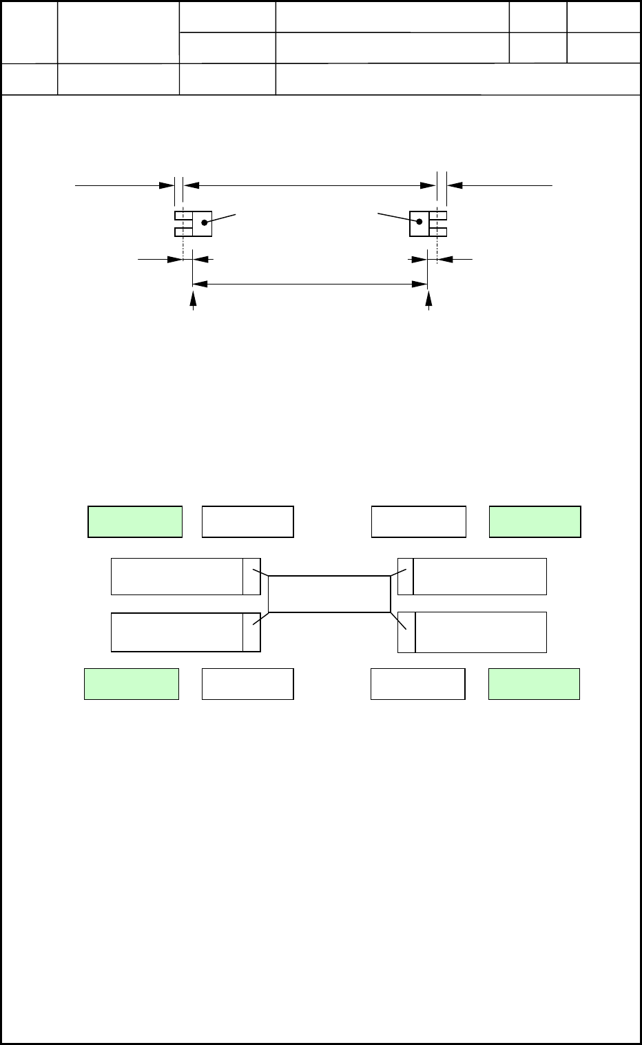
4. Location of Limit Sensors
4.1 Stroke between Limit Sensors
622±0.5 mm
4.2 Positions for Origin Adjustment
• The origin (+) must be adjusted on the motor mounting side.
• The origin (-) must be adjusted on the cutter replacement position (= Position for Origin
Adjustment).
1
Mechanical Stopper
-B6301(6302)
-B6302(6301)
622±0.5
1
Limit Photosensors
620
1
1
Origin Origin
Fig. I9 Location of Limit Sensors and Origins
Mechanical Stopper
Unit: mm
Cutter B
Cutter A Cutter C
Cutter D
Origin (+)Origin (-)
Motor
Origin (+)Origin (-)
Origin (-)Origin (+)
Origin (-)Origin (+)
Fig. I10 Positions for Origin Adjustment
-B6301
-B6302
0406-001
9-5