SM-131-006.pdf - 第199页
Device Name Chip Mounter Block Name Page No. Unit Name Revision Model Item GXH-1 Chapter 10 Nozzle Stocker 0406-001 10-4
Device
Name
Chip Mounter
Block Name
Page No.
Unit Name
Revision
Model ItemGXH-1
Chapter 10 Nozzle Stocker
2. Setting of Nozzle Stockers, Sensors, and Solenoid Valves
2.2 Adjustment of Each Nozzle Stocker Section
2.2.1 Setting of Nozzle Stocker Sensors
• Nozzle Stocker Unit Lower Limit Detection Sensor
Check that the emitted light cannot be received at the lower limit and can be received at the
upward movement.
• Nozzle Stocker Clamping Check Sensor
When a thickness gauge (0.3 mm) is inserted at the place (View B) in Fig. J4, the sensor
receives the emitted light ("Light Emitted and Received" Mode).
At the normal clamping, confirm that the emitted light is not received ("Light Emitted and
Not Received" Mode).
• Shutter Closing Check Sensor
Confirm that the sensor is changed from "ON" to OFF" after the shutter was moved 1 to 2
mm.
2.2.2 Adjustment of Nozzle Stocker Opening Stroke
Lock Cylinder Stroke Adjustment C in Fig. J4 at the position where the shutter is moved back
0.3 mm from the opening-blocked area with the shutter being open.
(Wrench 5.5 2 pcs. and Screw Lock 1401)
2.2.3 Adjustment of Nozzle Stocker Opening (Shutter) Speed
2.2.4 Adjustment of Nozzle Stocker Ascending Speed
0406-001
10-3
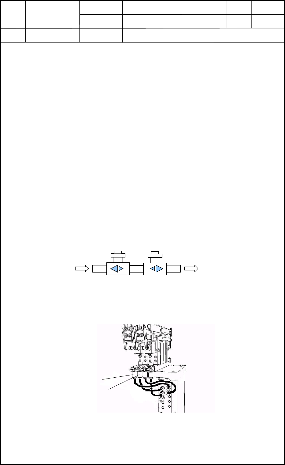
From the shutter valve
To the distribution joint
Fig. J5 Speed Controller
Ascent
Fig. J6 Stocker Ascent/Descent Adjustment Section
Descent

Device
Name
Chip Mounter
Block Name
Page No.
Unit Name
Revision
Model ItemGXH-1
Chapter 10 Nozzle Stocker
0406-001
10-4

Chapter 11
Recognition Section
This chapter describes how to replace the recognition
section.
• Replacement of PEC Recognition Camera
• Replacement of Component Recognition Camera
0406-001 11-A