SM-131-006.pdf - 第211页
0406-001 12-B

Chapter 12
Control Section
This chapter describes how to replace the control section.
• Replacement of CPU1
• Replacement of HDD
• Replacement of CPU2
• Replacement of Recognition Box
0406-001 12-A

0406-001 12-B
Device
Name
Chip Mounter
Block Name
Page No.
Unit Name
Revision
Model ItemGXH-1
Chapter 12 Control Section
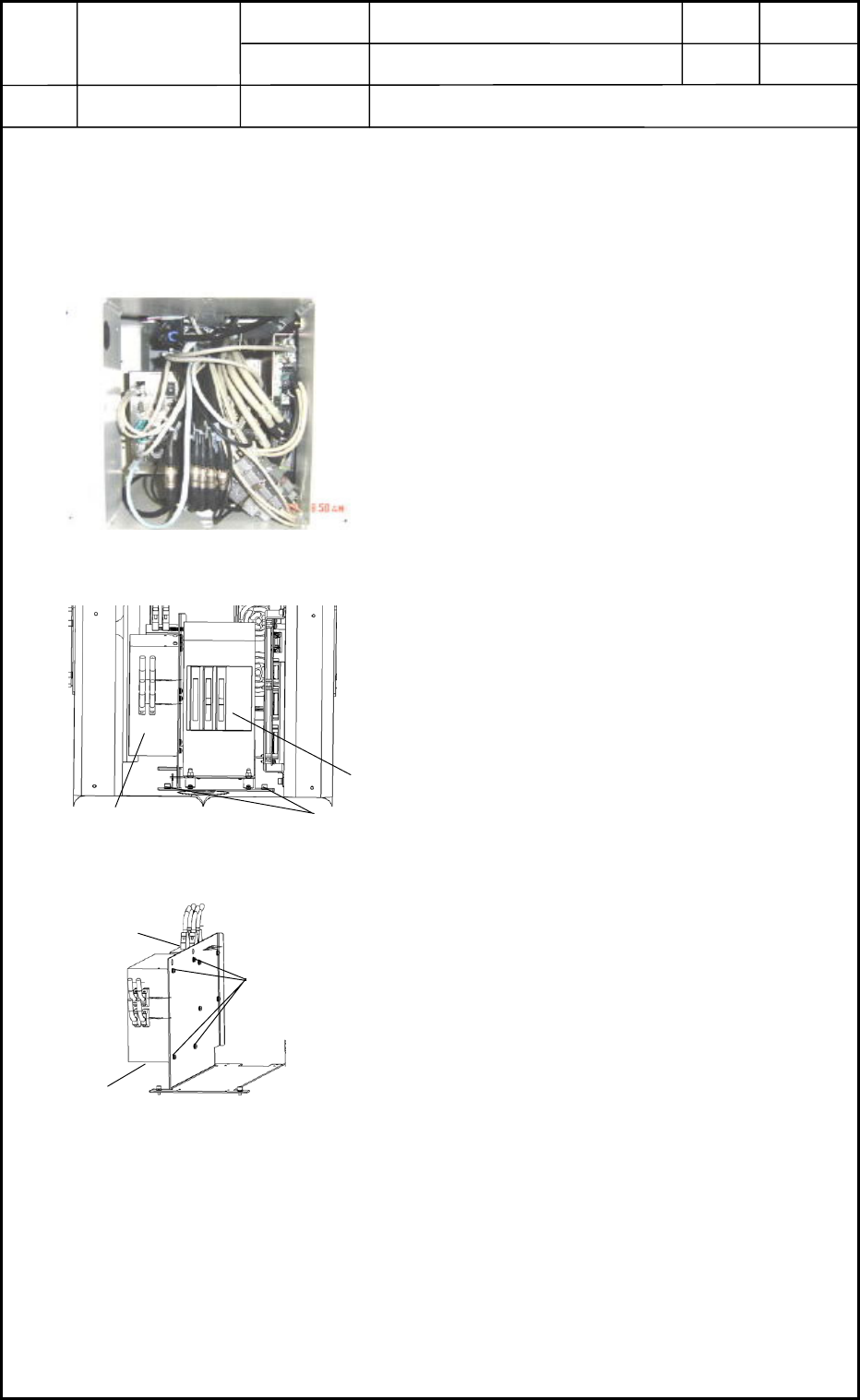
1. Replacement of CPU1
CPU1
• CPU1 is located under the frame on the rear side of the machine.
Refer to "1.7 Layout of FA Blocks" in Chapter 13 for details.
1.1 Detachment of CPU1
(1) Shut down the power to the machine.
(2) Detach the central cover on the rear side of the
machine. The contents are exposed as shown in
Fig. L1.
(3) Disconnect the connectors and loosen Setscrews
1 fastening the fixing panel in Fig. L2. After that,
pull out the control unit.
(4) Detach the recognition box first. See Fig. L3.
(5) Loosen Setscrew 2 (4 pcs.) in Fig. L3 and detach
CPU1.
1.2 Attachment of CPU1
Follow the reverse order of detachment to attach CPU1.
Fig. L1
CPU1
Setscrew 2
Fig. L3
0406-001
12-1
CPU1
Setscrew 1
Fig. L2
Selector
Recognition Box