SM-131-006.pdf - 第214页
Device Name Chip Mounter Block Name Page No. Unit Name Revision Model Item GXH-1 Chapter 12 Control Section 3. Replacement of CPU2 CPU2 • Two CPU2 boards are installed on this machine. Refer to "1.8 Layout of FB Blo…
Device
Name
Chip Mounter
Block Name
Page No.
Unit Name
Revision
Model ItemGXH-1
Chapter 12 Control Section
2. Replacement of HDD
CPU1
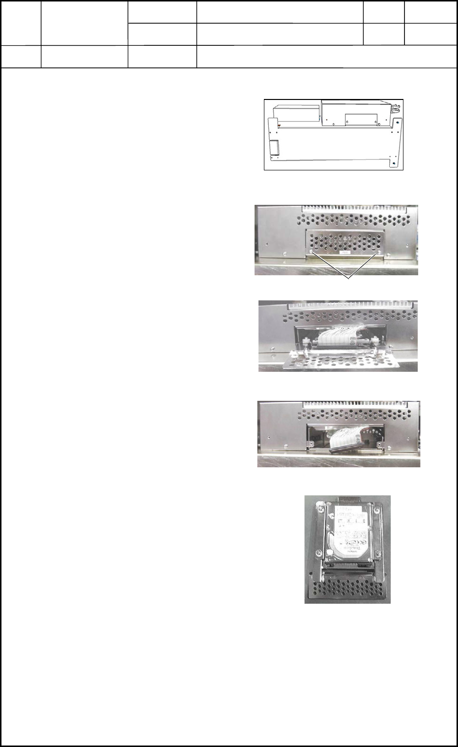
2.1 Detachment of HDD
(1) Take out CPU1 from the main
body and place and keep it under
the condition shown in Fig. L4.
Refer to "1.1 Detachment of
CPU1" for details.
(2) Loosen the anchor bolts.
(3) Pull out the cover and disconnect
the connector.
(4) When the cover is pulled out,
HDD also comes out together with
the cover.
(5) Loosen the four setscrews and
detach HDD.
2.2 Attachment of HDD
Follow the reverse order of detachment to attach HDD.
0406-001
12-2
Selector
CPU1
HDD
Fig. L4
Fig. L6 Detachment of Cover
Fig. L7 Disconnection of Connector
Fig. L8 HDD
Anchor Bolts
CPU1
Fig. L5
Device
Name
Chip Mounter
Block Name
Page No.
Unit Name
Revision
Model ItemGXH-1
Chapter 12 Control Section
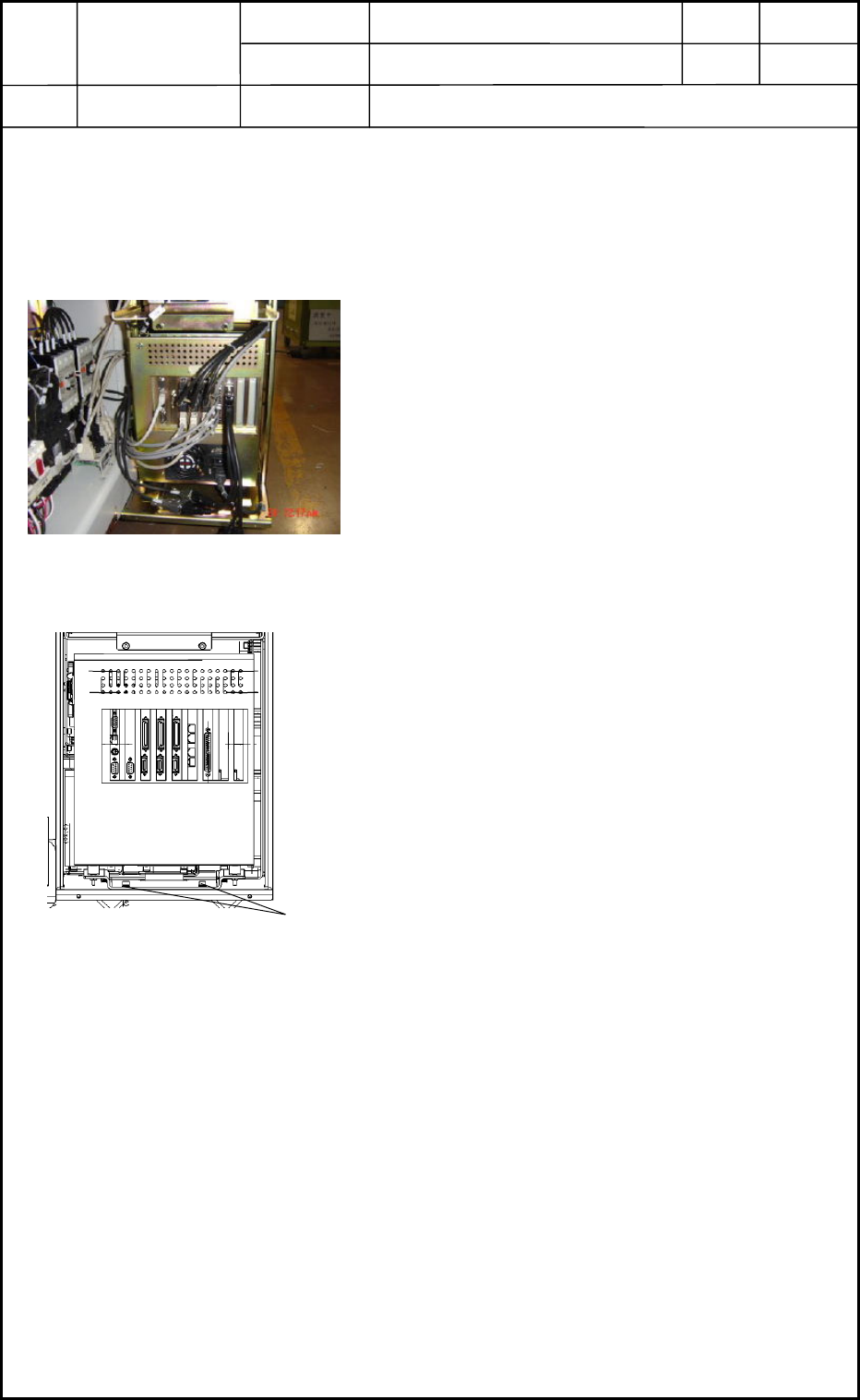
3. Replacement of CPU2
CPU2
• Two CPU2 boards are installed on this machine.
Refer to "1.8 Layout of FB Blocks" in Chapter 13 for details.
3.1 Detachment of CPU2
(1) Shut down the power to the machine.
(2) To expose CPU2 as shown in Fig. L9, detach the
cover of the main body from the side where the
object CPU2 is located.
(3) Disconnect the connectors. See Fig. L10.
(4) Loosen the anchor bolts shown in Fig. L10 and
detach CPU2.
3.2 Attachment of CPU2
Follow the reverse order of detachment to attach CPU2.
0406-001
12-3
Fig. L9
CPU2
Anchor Bolts
Fig. L10
Device
Name
Chip Mounter
Block Name
Page No.
Unit Name
Revision
Model ItemGXH-1
Chapter 12 Control Section
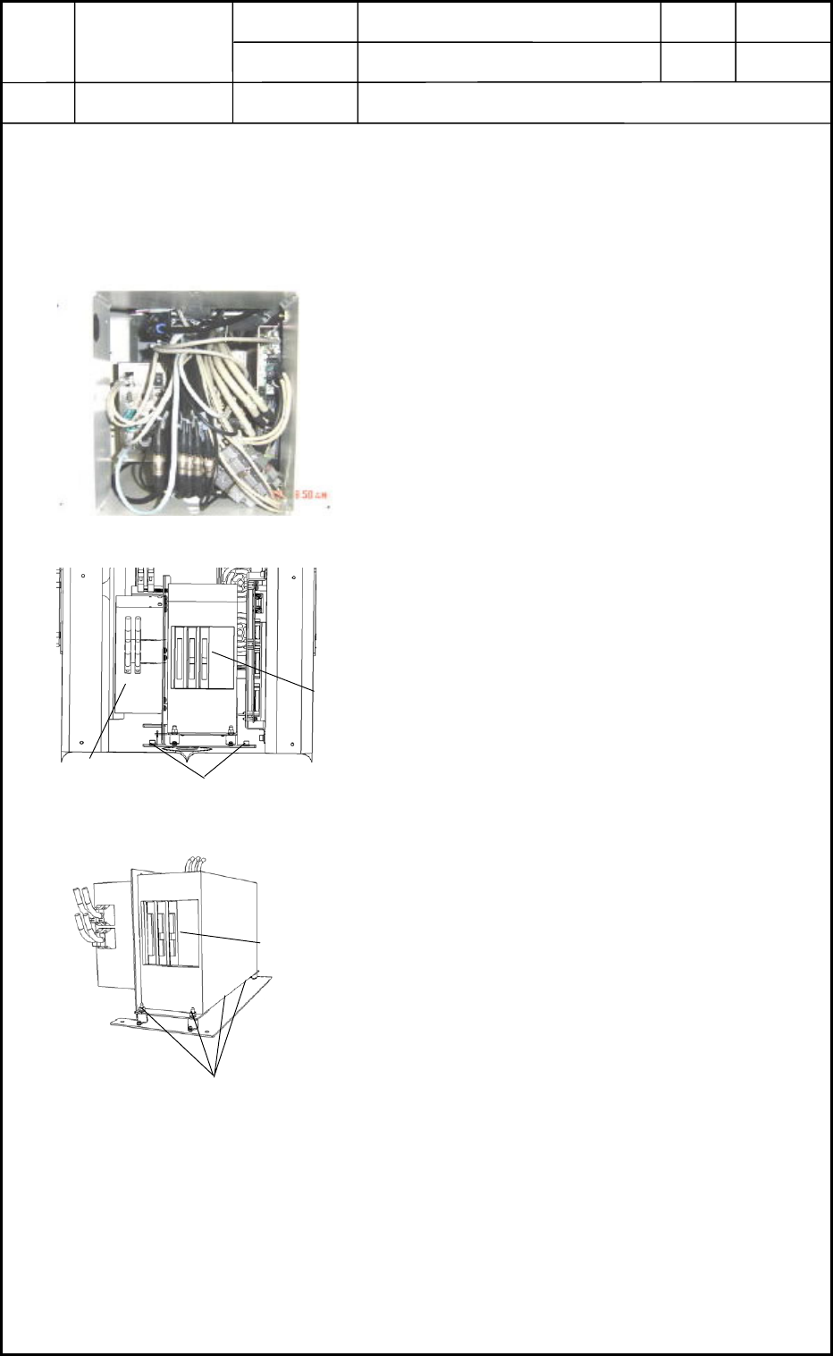
4. Replacement of Recognition Box
Recognition Box
• The recognition box is installed under the frame on the rear side of the machine.
Refer to "1.7 Layout of FA Blocks" in Chapter 13 for details.
4.1 Detachment of Recognition Box
(1) Shut down the power to the machine.
(2) Detach the central cover on the rear side of the
machine. The contents are exposed as shown in
Fig. L11.
(3) Disconnect the connectors to expose the
recognition box as shown in Fig. L12.
(4) Loosen Setscrew 1 fastening the fixing panel in
Fig. L12 and pull out the whole control unit.
(5) Loosen Setscrew 2 (4 pcs.) in Fig. L13 and
detach the recognition box.
4.2 Attachment of Recognition Box
Follow the reverse order of detachment to attach the recognition box.
0406-001
12-4
Fig. L11
CPU1
Setscrew 1
Fig. L12
Recognition Box
Setscrew 2
Fig. L13
Recognition Box