SM-131-006.pdf - 第216页
Chapter 13 Layout of Electrical Box This chapter describes the layout of the electrical box. • Layout of Underframe • Layout of Cutter & Component Recognition Camera • Layout of Nozzle Stocker Section • Layout of Fee…
Device
Name
Chip Mounter
Block Name
Page No.
Unit Name
Revision
Model ItemGXH-1
Chapter 12 Control Section
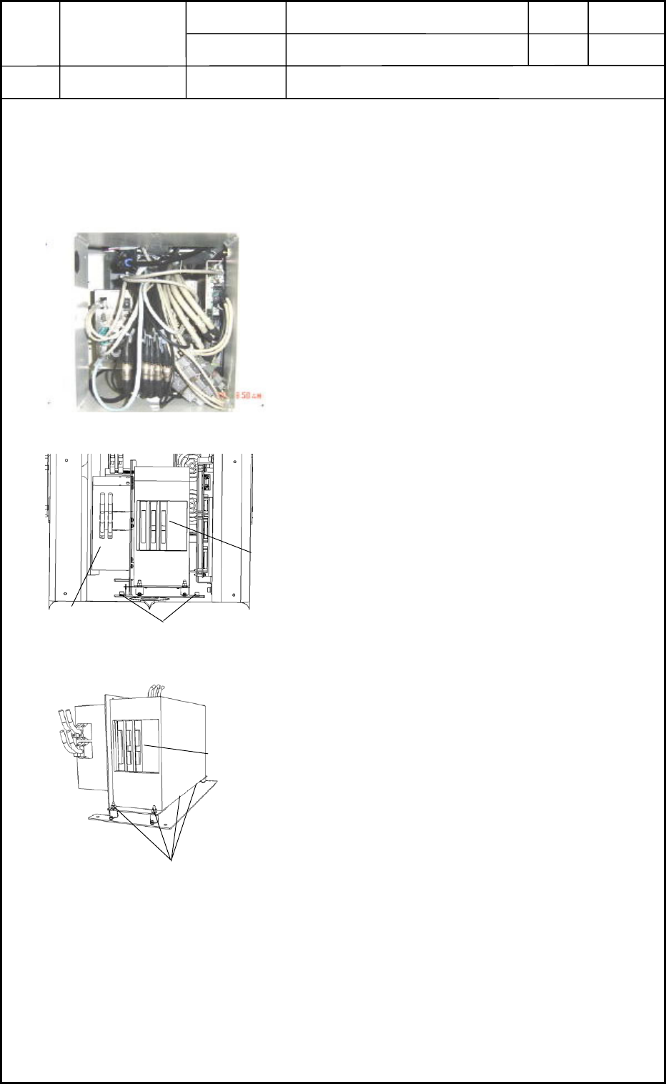
4. Replacement of Recognition Box
Recognition Box
• The recognition box is installed under the frame on the rear side of the machine.
Refer to "1.7 Layout of FA Blocks" in Chapter 13 for details.
4.1 Detachment of Recognition Box
(1) Shut down the power to the machine.
(2) Detach the central cover on the rear side of the
machine. The contents are exposed as shown in
Fig. L11.
(3) Disconnect the connectors to expose the
recognition box as shown in Fig. L12.
(4) Loosen Setscrew 1 fastening the fixing panel in
Fig. L12 and pull out the whole control unit.
(5) Loosen Setscrew 2 (4 pcs.) in Fig. L13 and
detach the recognition box.
4.2 Attachment of Recognition Box
Follow the reverse order of detachment to attach the recognition box.
0406-001
12-4
Fig. L11
CPU1
Setscrew 1
Fig. L12
Recognition Box
Setscrew 2
Fig. L13
Recognition Box

Chapter 13
Layout of Electrical Box
This chapter describes the layout of the electrical box.
• Layout of Underframe
• Layout of Cutter & Component Recognition Camera
• Layout of Nozzle Stocker Section
• Layout of Feeder Base Section
• Layout of Feeder Base Mechanical Section
• Layout of Transfer Section
• Layout of Beam Section
• Layout of Head Section
• Layout of Various Boards
• Layout of Each DC Power Units
• Layout of Robot Cable Connection Panel
• Layout of Covers
• Layout of Fans
0406-001 13-A

0406-001 13-B