SM-131-006.pdf - 第217页
0406-001 13-B

Chapter 13
Layout of Electrical Box
This chapter describes the layout of the electrical box.
• Layout of Underframe
• Layout of Cutter & Component Recognition Camera
• Layout of Nozzle Stocker Section
• Layout of Feeder Base Section
• Layout of Feeder Base Mechanical Section
• Layout of Transfer Section
• Layout of Beam Section
• Layout of Head Section
• Layout of Various Boards
• Layout of Each DC Power Units
• Layout of Robot Cable Connection Panel
• Layout of Covers
• Layout of Fans
0406-001 13-A

0406-001 13-B
Device
Name
Chip Mounter
Block Name
Page No.
Unit Name
Revision
Model ItemGXH-1
Chapter 13 Layout of Electrical
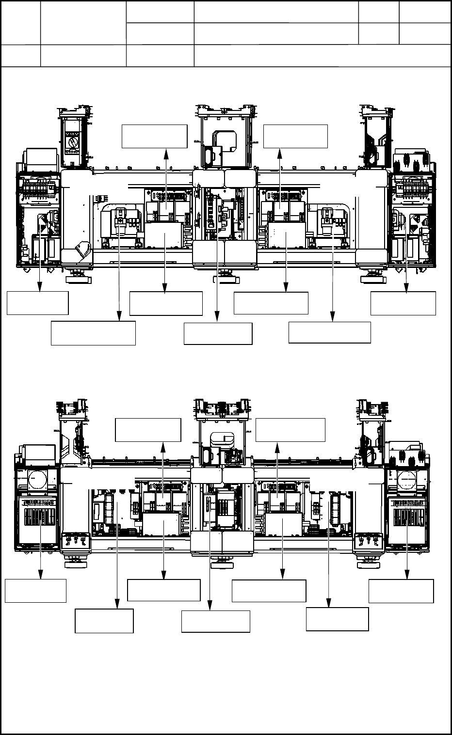
1. Layout of Underframe
Layout
1.1 Whole View of Underframe
0406-001
13-1
Lighting Unit
Section D
Section B
Vacuum Pump
Vacuum Pump
Lighting Unit
BH Block
BL Block
BR Block
BF Block BF Block
Fig. M1 Front Side of Machine
BF Block
Section A
Section C
BF Block
Lighting Unit
BC Block
BA Block
Lighting Unit
FA Block
CPU2 (R)
CPU2 (L)
Fig. M2 Rear Side of Machine