SM-131-006.pdf - 第230页
Device Name Chip Mounter Block Name Page No. Unit Name Revision Model Item GXH-1 Chapter 13 Layout of Electrical 1. Layout of Underframe Layout 1.9 Layout of BF Blocks Symbol Name A21 X-Axis Servoam p lifier A22 Y1-Axis …
Device
Name
Chip Mounter
Block Name
Page No.
Unit Name
Revision
Model ItemGXH-1
Chapter 13 Layout of Electrical
1. Layout of Underframe
Layout
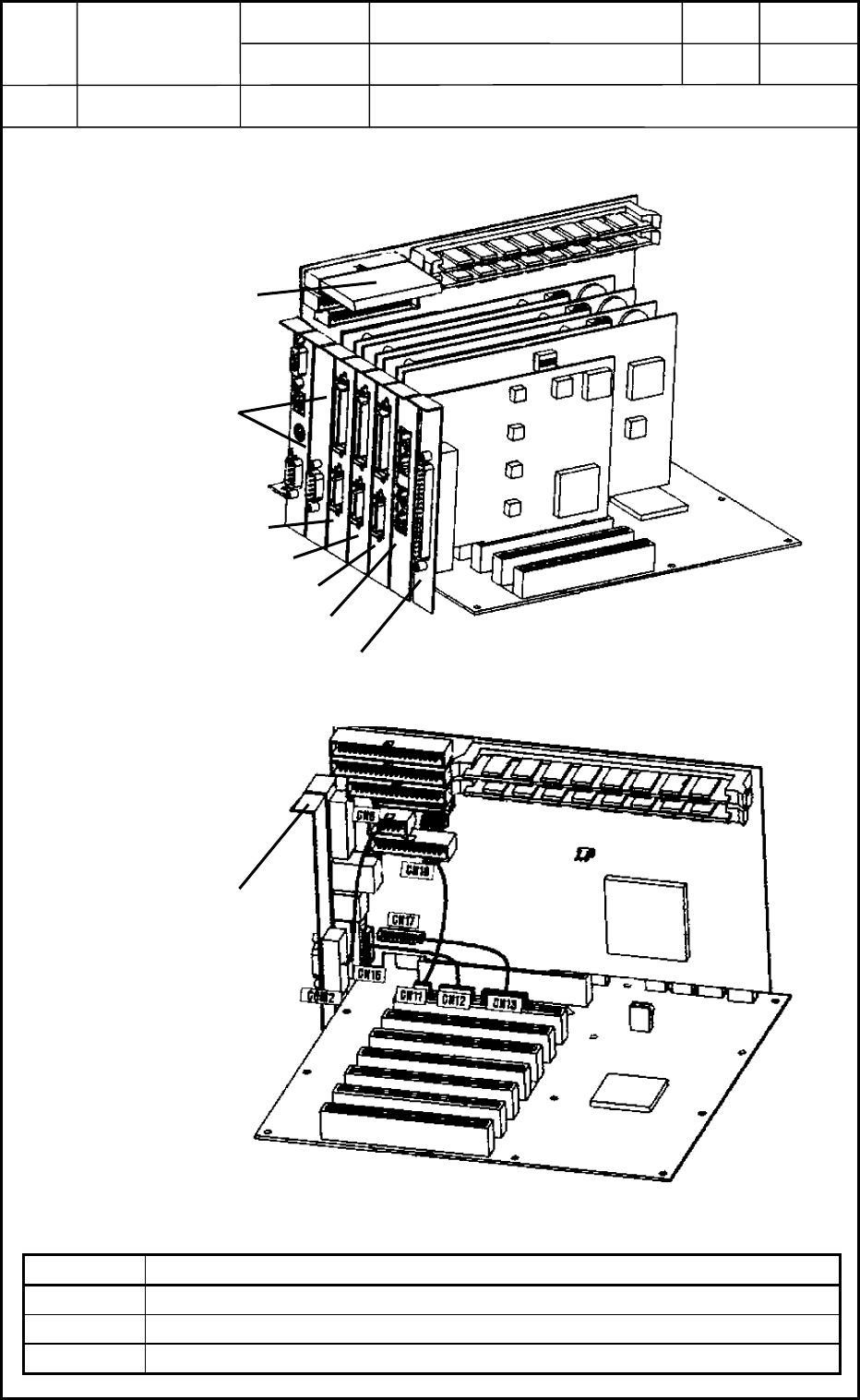
1.8 Layout of FB Blocks
Symbol Name
U82 Motion Control Board
U83 Motion Control Board
U84 Motion Control Board
0406-001
13-12
Memory Card
CPU Board
U82
U83
U84
HLS Centerboard
SERIAL Communication Board
Fig. M34 Internal View of CPU2
CPU Board
COM2 Pullout Panel
Back Plane
Fig. M35 Internal Connections of CPU2
Device
Name
Chip Mounter
Block Name
Page No.
Unit Name
Revision
Model ItemGXH-1
Chapter 13 Layout of Electrical
1. Layout of Underframe
Layout
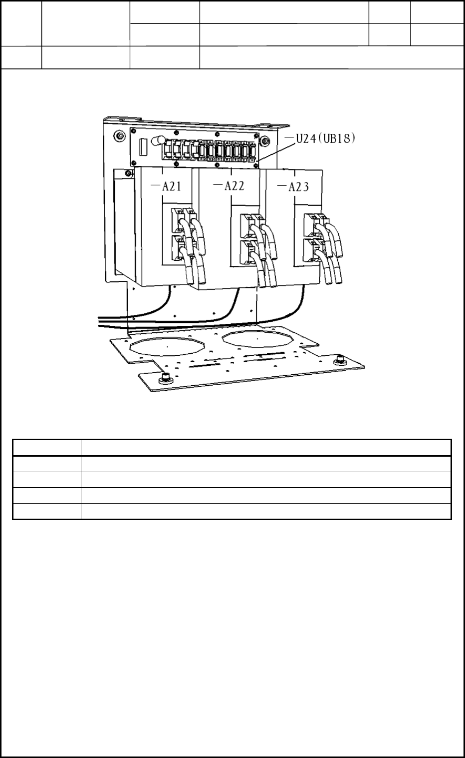
1.9 Layout of BF Blocks
Symbol Name
A21 X-Axis Servoamplifier
A22 Y1-Axis Servoamplifier
A23 Y2-Axis Servoamplifier
U24 Beam Relay Board UB18
0406-001
13-13
Fig. M36 Arrangement of Beam Amplifiers
Device
Name
Chip Mounter
Block Name
Page No.
Unit Name
Revision
Model ItemGXH-1
Chapter 13 Layout of Electrical
2. Layout of Cutter & Component Recognition Camera
Layout
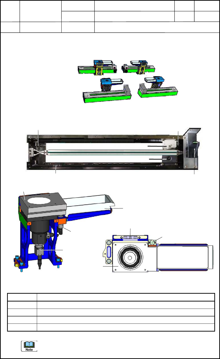
2.1 Layout of Cutter & Component Recognition Camera
Symbol Name
M63 Cutter Axis Motor
B6301 Cutter (+) Origin Sensor
B6302 Cutter (-) Origin Sensor
B61 Component Recognition Camera
The (+) origin sensor is located on the motor mounting side and the (-) origin sensor on the
cutter replacement position side.
0406-001
13-14
Rear Side
Front Side
Section A
Section B
Section C
Section D
Fig. M37 Cutter & Component Recognition Camera
M63
B6301
B6302
Upper Blade
Lower Blade
Belt
Fig. M38 Cutter Unit
Lighting Unit
B61
Lighting Fiber
Component Storage Box
Lighting Unit
Glass Jig Base
Mark for Teaching
(From the front left side)
(Top View)
Component
Storage Box
Fig. M39 Component Recognition Camera