SM-131-006.pdf - 第233页
Device Name Chip Mounter Block Name Page No. Unit Name Revision Model Item GXH-1 Chapter 13 Layout of Electrical 4. Layout of Feeder Base Section Layout Fig. M44 Internal View of Feeder Base Cylinder B6951 Clamp Lever Y6…
Device
Name
Chip Mounter
Block Name
Page No.
Unit Name
Revision
Model ItemGXH-1
Chapter 13 Layout of Electrical
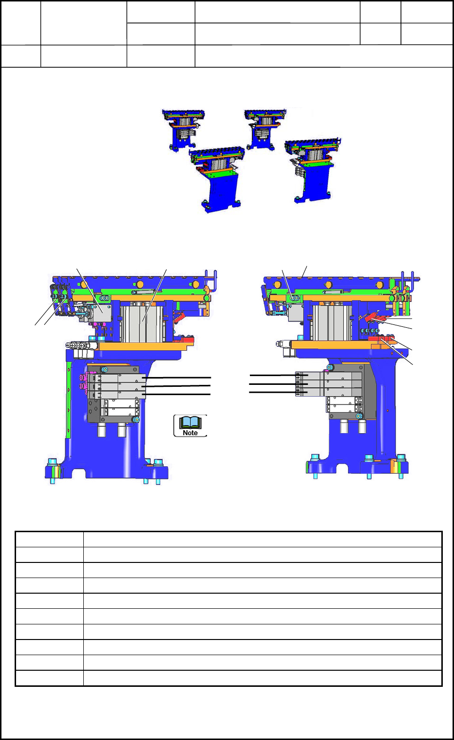
3. Layout of Nozzle Stocker Section
Layout
3.1 Layout of Nozzle Stocker Section
Symbol Name
B0918 Nozzle Stocker Unit Lower Limit Detection Sensor 1
B0919 Nozzle Stocker Unit Lower Limit Detection Sensor 2
B0920 Nozzle Stocker Shutter Closing Check Sensor 1
B0921 Nozzle Stocker Shutter Closing Check Sensor 2
B0922 Nozzle Stocker Clamping Check Sensor 1
B0923 Nozzle Stocker Clamping Check Sensor 2
Y0935 Nozzle Stocker Shutter Opening Valve
Y0936 Nozzle Stocker Ascending 1
Y0937 Nozzle Stocker Ascending 2
Section A
Section B
Section D
Rear Side
Front Side
Fi
g
. M40 Whole View of Nozzle Stockers
Section C
B0922
B0918
Y0937
Y0936
Y0935
B0923
B0919
B0921
(
B0920
)
Shutter
Open/Close Cylinder
Stocker
Up/Down Cylinder
(From the front left side)
(From the front right side)
2
1
Order of Nozzle
Stockers: Nos. 1 and 2 of
Devices
Fig. M41 Nozzle Stocker
0406-001
13-15
Device
Name
Chip Mounter
Block Name
Page No.
Unit Name
Revision
Model ItemGXH-1
Chapter 13 Layout of Electrical
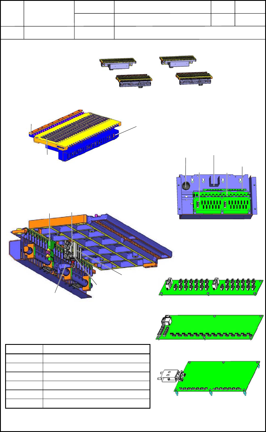
4. Layout of Feeder Base Section
Layout
Fig. M44 Internal View of Feeder Base
Cylinder
B6951
Clamp Lever
Y6930
B6950
4.1 Feeder Base Section
Symbol Name
UB16 Serial Board
UB17 Relay Board
UB24 HLS Board
Y6930 Valve for Feeder Clamping
B6950 Feeder Clamping Lower Limit Sensor
B6951 Feeder Clamping Upper Limit Sensor
Section A
Section B
Section C
Section D
Rear Side
Front Side
Fig. M42 Whole View of Feeder
Feeder Connector
(Nos. 1 through 25)
Feeder
Positioning Pin
Guide
Fig. M43 Feeder Base
Fig. M47 UB24
Fig. M46 UB17
Fig. M48 UB16
Fig. M45 Feeder Base Electrical Box
UB17
UB24
UB16
Cylinder
Protective Cover
Batch Connector Inlet
0406-001
13-16
Device
Name
Chip Mounter
Block Name
Page No.
Unit Name
Revision
Model ItemGXH-1
Chapter 13 Layout of Electrical
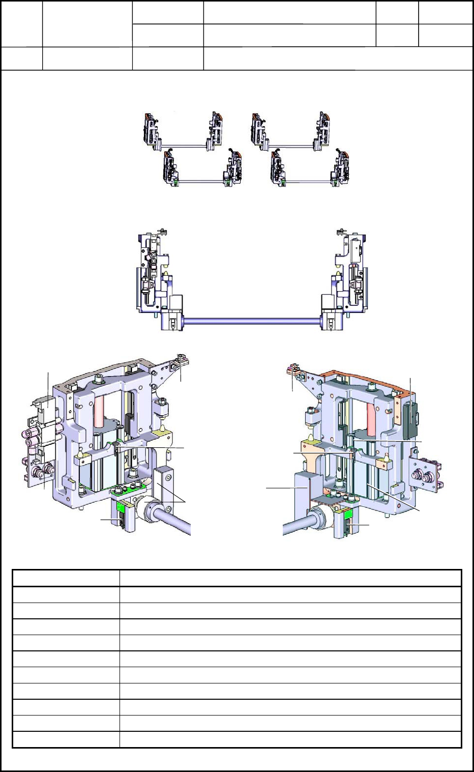
5. Layout of Feeder Base Mechanical Section
Layout
5.1 Layout of Feeder Base Mechanical Section
Symbol Name
B0510T
Suppressor Detection Sensor (Light Emission)
B0510
Suppressor Detection Sensor (Light Reception)
B0910
Feeder Base Y-Direction Positioning Check Sensor 1
B0911
Feeder Base Y-Direction Positioning Check Sensor 1
B0912
Lift Section Feeder Base Detection Sensor 1
B0913
Lift Section Feeder Base Detection Sensor 1
B0914
Cylinder Upper Limit Detection Sensor
B0915
Cylinder Lower Limit Detection Sensor
Y0932
Feeder Base Ascending Valve
Y0933
Feeder Base Descending Valve
0406-001
13-17
Fig. M49 Whole View of Feeder Base
Front Side
Rear Side
Section A
Section B
Section C
Section D
Fig. M50 Feeder Base Mechanical Section
Right Side
Left Side
B0913
Y0933
Gear Section
Gear Cover
Fig. M51 Magnified View of Left Side
B0510
B0910
Y0932
Fig. M52 Magnified View of Right Side
B0510T
Amplifier of B0510
B0912
B0914
B0915
B0911