SM-131-006.pdf - 第238页
Device Name Chip Mounter Block Name Page No. Unit Name Revision Model Item GXH-1 Chapter 13 Layout of Electrical 7. Layout of Beam Section Layout 7.1 Layout of Beam Section 0406-001 13-21 Y2 Axis Y1 Axis Y1 Axis Y2 Axis …
Device
Name
Chip Mounter
Block Name
Page No.
Unit Name
Revision
Model ItemGXH-1
Chapter 13 Layout of Electrical
6. Layout of Transfer Section
Layout
Symbol Name
M41 Motors for Transfers in NL and NR Sections
M42 Motors for Transfers in NA and NC Sections
M43 Motor for Transfer in NC Section
M51 Width Adjusting Motor in NL and NR Sections
M52 Width Adjusting Motor in NL and NR Sections
M53 Motors for Backup Axes in NA and NC Sections
M55 Motor for Chute Width Adjusting Axis
M56 Motor for Chute Width Adjusting Axis
B4101 PCB Detection Sensors (Deceleration) in NL and NR Sections
B4102 PCB Detection Sensors (Stop) in NL and NR Sections
B4201 PCB Detection Sensors (Deceleration) in NA and NC Sections
B4202 PCB Detection Sensors (Stop) in NA and NC Sections
B4401 PCB Detection Sensor (Deceleration) in NB Section
B4402 PCB Detection Sensor (Stop) in NB Section
B5101 Chute Width Variable Sensors (+) Limit in NL and NR Sections
B5201 Chute Width Variable Sensors (-) Limit in NL and NR Sections
B5501 Chute Width Variable Sensor (+) Limit in NB Section
B5601 Chute Width Variable Sensor (-) Limit in NB Section
B5301 Backup (+) Limit Sensors in NA and NC Sections
B0814 NA and NC Backup Plate Check Sensor 1
B0815 NA and NC Backup Plate Check Sensor 2
B0810 PCB Stopper 1 Upper Limit Sensor in NL Section
B0811 PCB Stopper 1 Lower Limit Sensor in NL Section
YSV0830 PCB Stopper Cylinder Valve in NL Section
YSV0834 Z Clamp Cylinder Valves A in NA and NC Sections
YSV0835 Z Clamp Cylinder Valves B in NA and NC Sections
YSV0836 Z Clamp Cylinder Valves A in NA and NC Sections
0406-001
13-20
Device
Name
Chip Mounter
Block Name
Page No.
Unit Name
Revision
Model ItemGXH-1
Chapter 13 Layout of Electrical
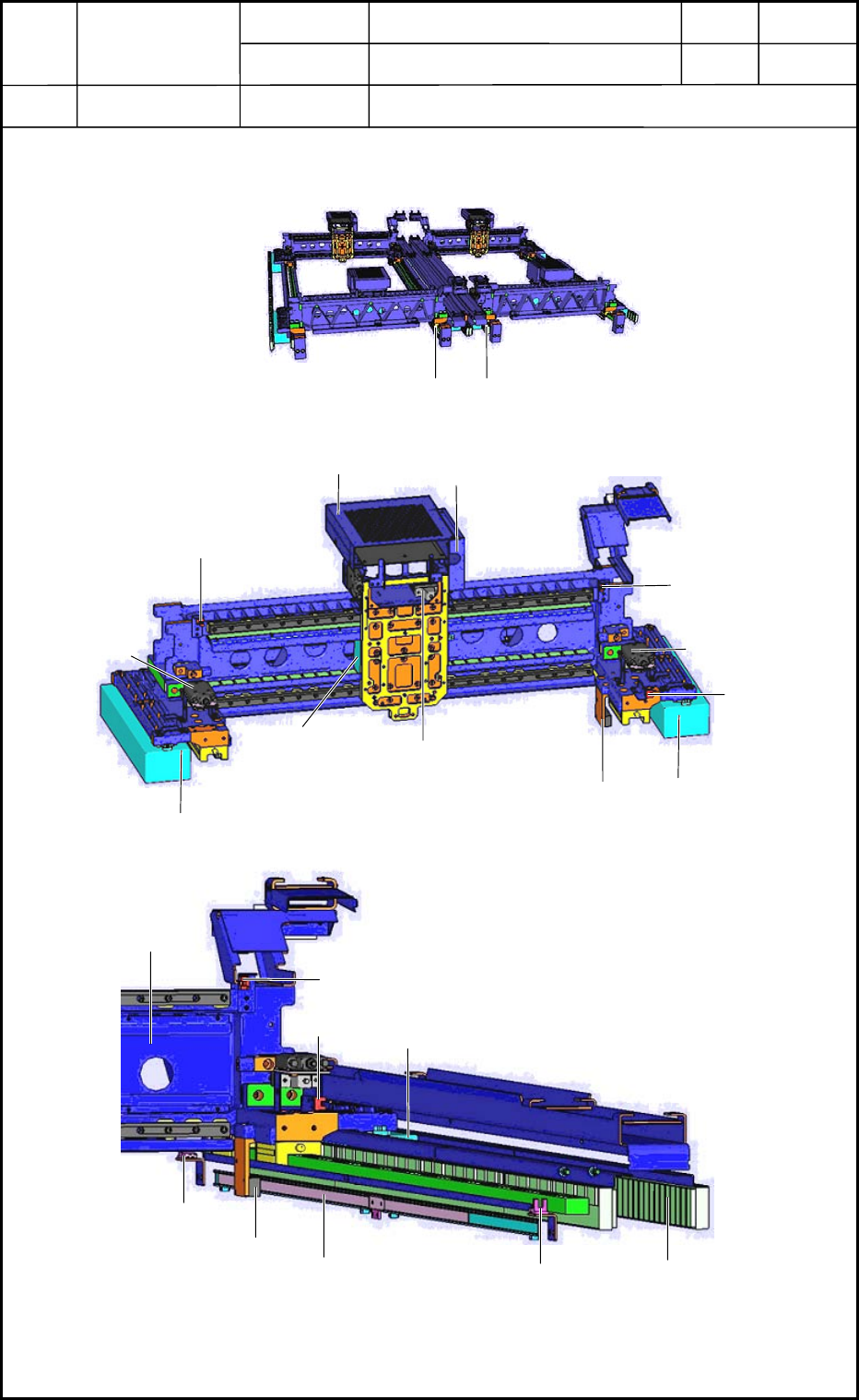
7. Layout of Beam Section
Layout
7.1 Layout of Beam Section
0406-001
13-21
Y2 Axis
Y1 Axis
Y1 Axis
Y2 Axis
X Axis in Section A
X Axis in Section B
X Axis in Section C
X Axis in Section D
Fig. M59 Whole View of Beams
B2101
M23
M21
M22
B2102
Encoder
Y1-Axis Converter
B2202
U03
Head Wiring
X-Axis Converter
Fig. M60 Magnified View of X Axis
Y2-Axis
Converter
Motor Stator
B2202
M22
Encoder
Scale
B2201
B2203
X Axis
B2102
Fig. M61 Magnified View of Y1 Axis

Device
Name
Chip Mounter
Block Name
Page No.
Unit Name
Revision
Model ItemGXH-1
Chapter 13 Layout of Electrical
7. Layout of Beam Section
Layout
Symbol Name
U03 Amplifier Board for Linear Measure Sensor
M21 X-Axis Motor
M22 Y1-Axis Motor
M23 Y2-Axis Motor
B2101 X-Axis Limit Sensor (+)
B2102 X-Axis Limit Sensor (-)
B2201 Y-Axis Limit Sensor (+)
B2202 Y-Axis Approach Detection Sensor
B2203 Y-Axis Limit Sensor (-)
0406-001
13-22