SM-131-006.pdf - 第244页
Device Name Chip Mounter Block Name Page No. Unit Name Revision Model Item GXH-1 Chapter 13 Layout of Electrical 12. Layout of Covers Layout 12.1 Layout of Covers A C4 B C2 C1 D1 E1 C3 D2 D4 D3 E2 E3 E4 F2 F1 F4 F3 G2 G1…
Device
Name
Chip Mounter
Block Name
Page No.
Unit Name
Revision
Model ItemGXH-1
Chapter 13 Layout of Electrical
11. Layout of Robot Cable Connection Panel
Layout
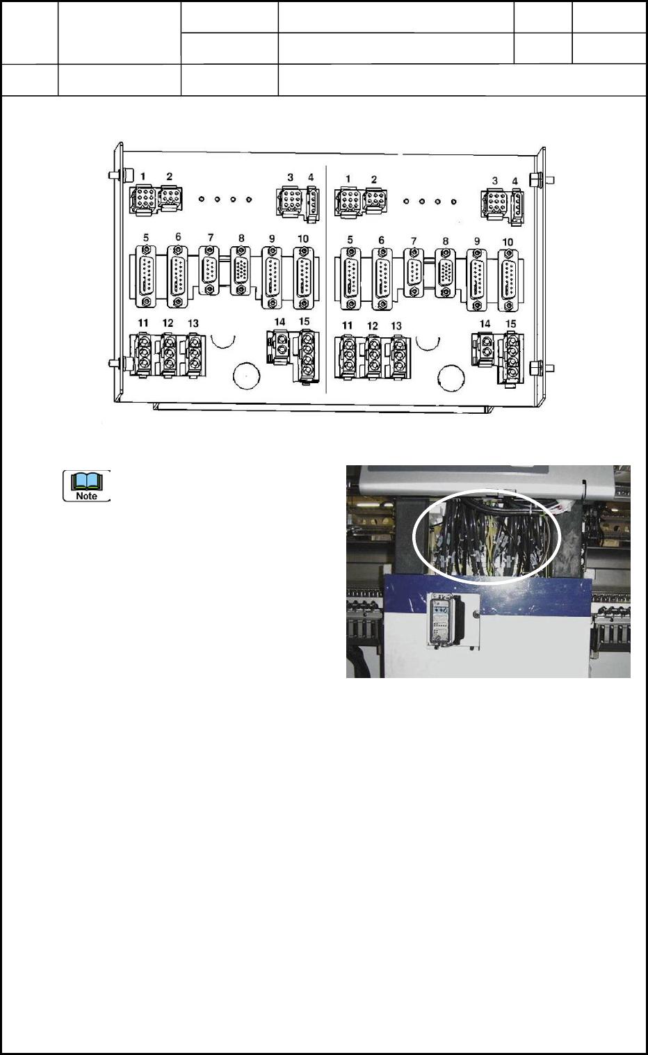
11.1 Layout of Robot Cable Connection Panel
The robot cable connection panel is
located inside the cover under the
operation monitor. See Fig. M68.
(Two panels are used - One located on
the front side of the machine and the
Other on the rear side.)
Description of Each Connector
1. Connector for Lighting Lamp Cable (For Lighting of P.E.C. Recognition Camera)
2. Connector for Interlock Cable (For Head Up/Down Sensor)
3. Connector for X-Axis Limit Sensor Cable
4. Reserved Connector
5. Connector for Encoder Cable of X-Axis Motor
6. Connector for SSCNET Cable (For Signal from Head Multiaxis Board)
7. Connector for LINK Cable (For Slip Ring and Linear Measure Sensor Signal)
8. Connector for Camera Cable (For P.E.C. Recognition Camera)
9. Connector for Encoder Cable of Y1-Axis Motor
10. Connector for Encoder Cable of Y2-Axis Motor
11. Connector for Power Supply Cable of Y1-Axis Motor
12. Connector for Power Supply Cable of Y2-Axis Motor
13. Connector for Power Supply Cable of X-Axis Motor
14. Connector for 48 V DC Cable of Head Multiaxis Board (For Head Multiaxis Board)
15. Connector for 24 V DC Cable (For UB25 Board)
0406-001
13-26
Fig. M67 Robot Cable Connection Panel
Side B (Side C)
Side D (Side A)
Fig. M68 Location of Robot Cable Connection Panel
Device
Name
Chip Mounter
Block Name
Page No.
Unit Name
Revision
Model ItemGXH-1
Chapter 13 Layout of Electrical
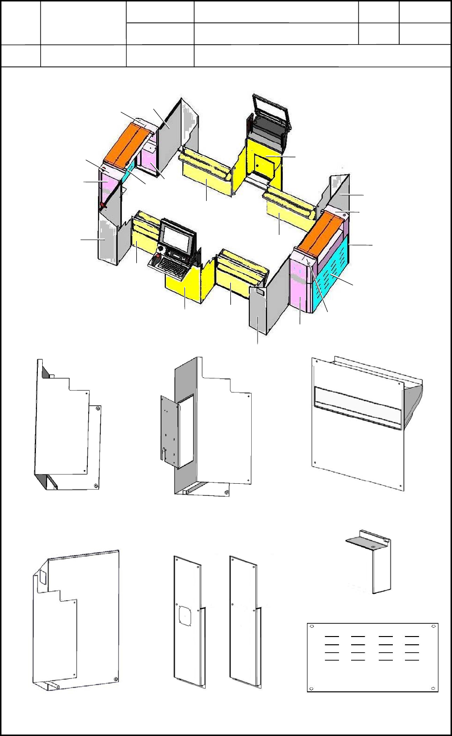
12. Layout of Covers
Layout
12.1 Layout of Covers
A
C4
B
C2
C1
D1
E1
C3
D2
D4
D3
E2
E3
E4
F2
F1
F4
F3
G2
G1
Fig. M69 Whole View of Covers
Fig. M70 Magnified View of A
Fig. M71 Magnified View of B
Fig. M72 Magnified View of C
Fig. M73 Magnified View of D Fig. M74 Magnified View of E
Fig. M75 Magnified View of F
Fig. M76 Magnified View of G
0406-001
13-27
Device
Name
Chip Mounter
Block Name
Page No.
Unit Name
Revision
Model Item GXH-1
Chapter 13 Layout of Electrical Box
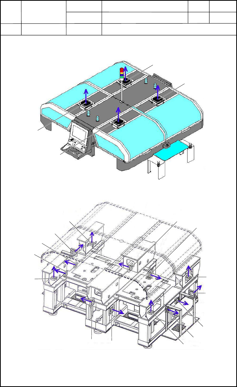
13. Layout of Fans
Layout
13.1 Layout of Fans
M103
M104
M102
M101
Fig. M77 Cover Section
M111
M108
M110
M109
M107
M105
M112
M114
M116
M117
M118
M115
M113
M106
Fig. M78 Frame Section
0406-001
13-28