SM-131-006.pdf - 第249页
0406-001 15-B

Chapter 15
Others
This chapter describes the others.
• Attachment of Operation Monitor
0406-001 15-A

0406-001 15-B
Device
Name
Chip Mounter
Block Name
Page No.
Unit Name
Revision
Model ItemGXH-1
Chapter 15 Others
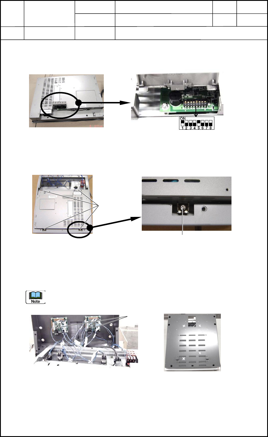
2. Attachment of Operation Monitor
2.1 Setting of Operation Monitor
Set the dip switches located on the back of the operation monitor. (Fig. O1)
2.2 Fix the monitor to the frame.
Fix the operation monitor to the frame with four fixtures.
2.3 Connect the connector to the operation board.
Insert the connector to the UB13 board for operations (Fig. O3) and attach the cover with
seven bolts as shown in Fig. O4.
Do not make a mistake in connector insertion (R and L Sides).
0406-001
15-1
Fig. O1
Fixtures
Fixture
Fig. O2
Fig. O4
UB13
Fig. O3