SM-131-006.pdf - 第252页
Device Name Chip Mounter Block Name Page No. Unit Name Revision Model Item GXH-1 Chapter 15 Others 2. Attachment of Operation Monitor 2.7 Operation Check Supply power to the machine and check opera tion of the monitor af…
Device
Name
Chip Mounter
Block Name
Page No.
Unit Name
Revision
Model ItemGXH-1
Chapter 15 Others
2. Attachment of Operation Monitor
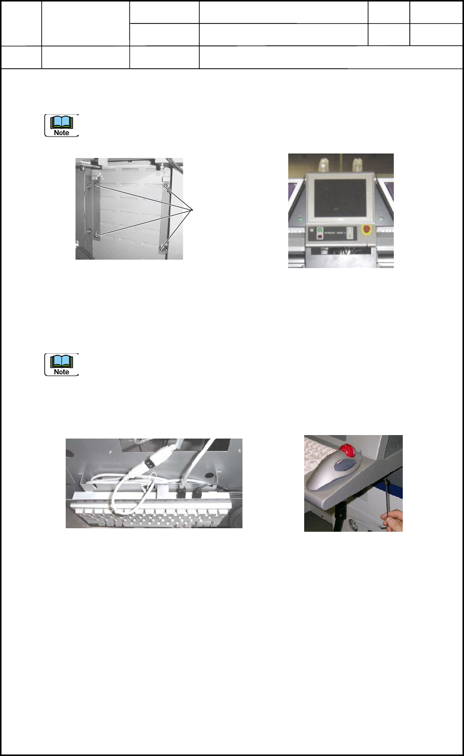
2.4 Attachment of Operation Monitor to Main Machine
Attach the operation monitor to the main machine. (Fig. O5)
Fix the monitor, keeping both right and left sides of the monitor horizontal, and adjust the
height so that the upper side of the monitor can be aligned with the ceiling of the machine.
(Fig. O6)
2.5 Cable Connection
Connect the cables running from the main machine with the boards (UB13) for the monitor
and the operation.
Do not make a mistake in connector insertion (R and L Sides).
2.6 Attachment of Keyboard
After the USB connections (Fig. O7), attach the keyboard. (Fig. O8)
Fig. O6
Fig. O5 Back of Monitor
Anchor Bolts
Fig. O7 USB Connections (2 Places)
Fig. O8
0406-001
15-2
Device
Name
Chip Mounter
Block Name
Page No.
Unit Name
Revision
Model ItemGXH-1
Chapter 15 Others
2. Attachment of Operation Monitor
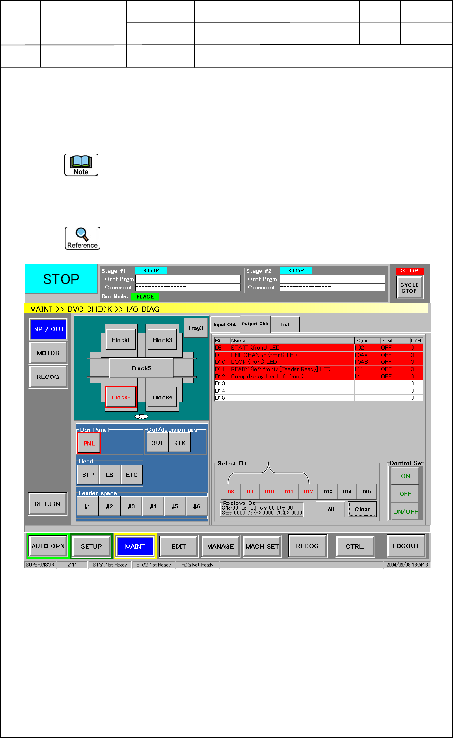
2.7 Operation Check
Supply power to the machine and check operation of the monitor after the attachment.
(1) Open the "I/O DIAG" window shown in Fig. O9. (Operation Sequence: [SUPERVISOR]
Button → [MAINT] Button → [DVC CHECK] Button)
Follow the steps below to check operation of the front operation monitor after the
attachment. The same steps must be followed fro the rear operation panel.
(2) Select the [Block2] and [PNL] buttons and then the "Output Chk" tab.
(3) Select "D8" through "D12" (Bits) individually. Press the [ON] button in the "Control
Sw" group box and check the ON/OFF status of the object LED.
When the LED on the "Block4" side is turned ON, it indicates that a wrong cable is
connected.
Bit Selection
Fig. O9
0406-001
15-3
Device
Name
Chip Mounter
Block Name
Page No.
Unit Name
Revision
Model ItemGXH-1
Chapter 15 Others
2. Attachment of Operation Monitor
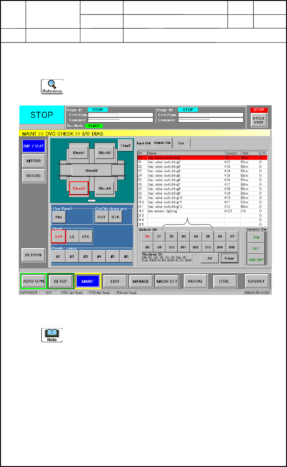
(4) Select the [Block2] and [STP] buttons and then the "Output Chk" tab. (Fig. O10)
(5) Select an arbitrary "Bit" and press the [ON] button in the "Control Sw" group box. Check
if a vacuum sound can be heard from the head on the objective side.
When a vacuum sound can be heard from the head on the "Block4" side, it indicates
that a wrong cable is connected.
(6) Follow the same steps as (2) through (5) to check operation of "Block4".
In the case of "Block4", the window in Fig. O9 cannot be used to check "START",
"PNL CHANGE", and "LOCK".
(7) When the results of the checking are normal, this work is completed.
0406-001
15-4
Bit Selection
Fig. O10