SM-131-006.pdf - 第307页
Device Name Chip Mounter Block Name Page No. Unit Name Revision Model Item GXH -1 Chapter 18 Pack aging 2. Packag ing Procedure 18-8 0512-001 Fig. R3- 7 Low er ing the machine onto the base Fig. R3- 8 Anchor on Steel Bas…
Device
Name
Chip Mounter
Block Name
Page No.
Unit Name
Revision
Model Item GXH-1
Chapter 18 Packaging
2. Packaging Procedure
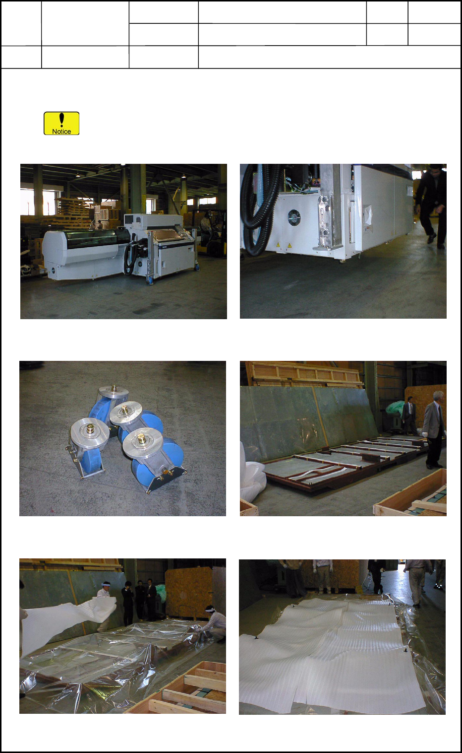
2.1 Packaging Procedure with Steel Panels
The photos below show how to package a component placement machine (TCM-X
series).
Follow the same procedure for the GXH series.
18-7
0512-001
Fig. R3-1 Component Placement
Machine before Packaging
Fig. R3-2 Detachment of Lifting Lugs
and Casters
Fig. R3-4 Base for Packaging with
Steel Panels
Fig. R3-5 Steel Base before
Covering with Sheet
Fi
g
. R3-6 Sheet-Covered Steel Base
Fig. R3-3 Detached Casters
Device
Name
Chip Mounter
Block Name
Page No.
Unit Name
Revision
Model Item GXH-1
Chapter 18 Packaging
2. Packaging Procedure
18-8
0512-001
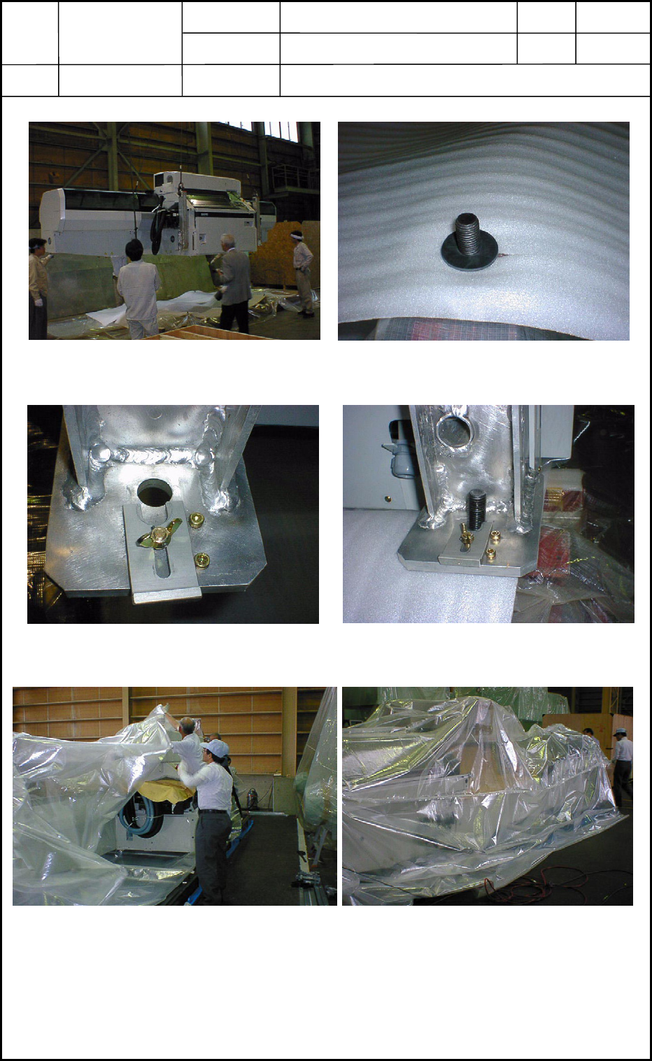
Fig. R3-7 Lowering the machine
onto the base
Fig. R3-8 Anchor on Steel Base
Fig. R3-9 Hole for Anchor of Lifting Lug
Fig. R3-11 Covering the machine with a sheet
Fig. R3-10 Anchor inserted into Lifting Lug
Fig. R3-12 Sheet Hems bonded by
thermo-compression
Device
Name
Chip Mounter
Block Name
Page No.
Unit Name
Revision
Model Item GXH-1
Chapter 18 Packaging
2. Packaging Procedure
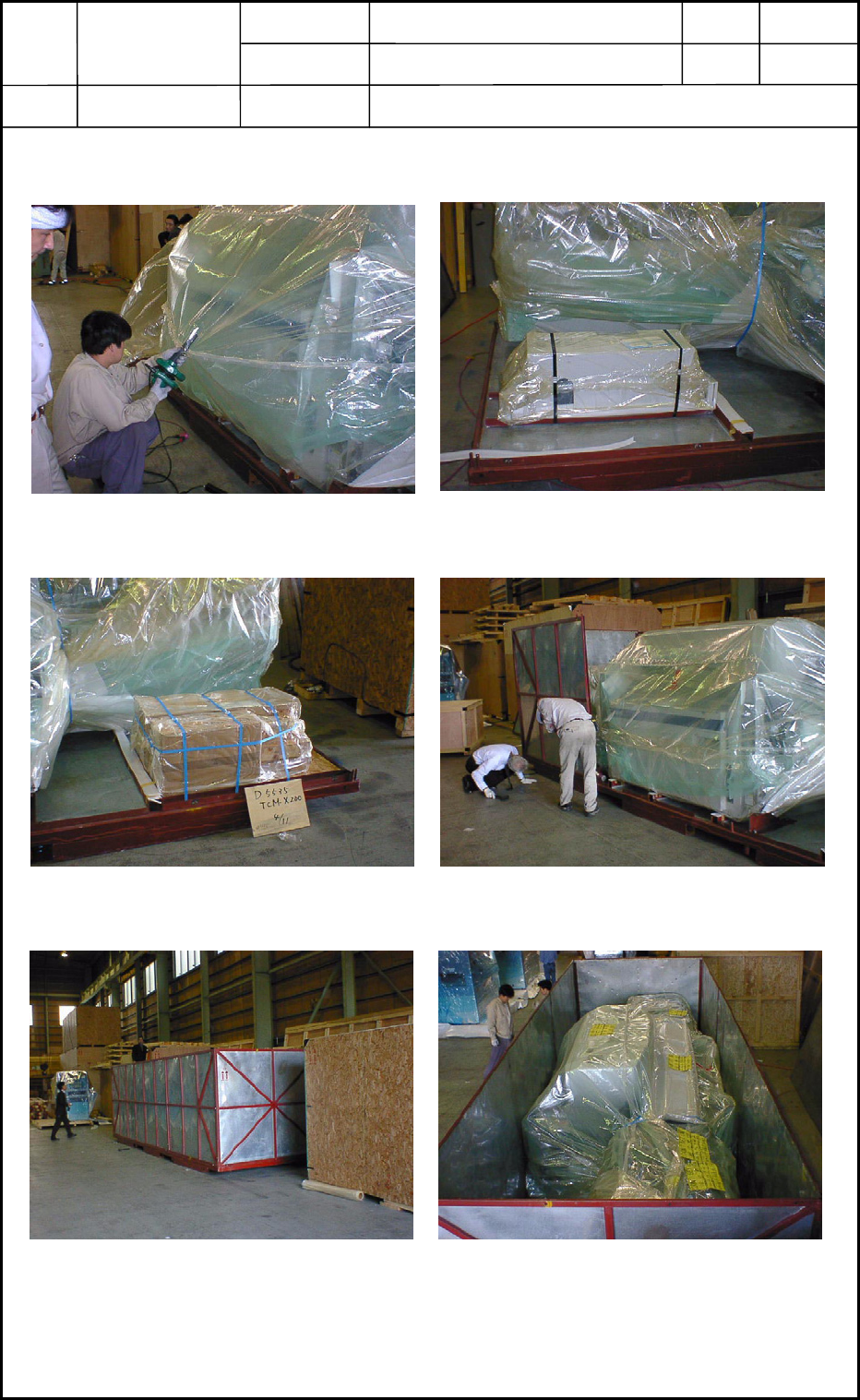
Fig. R3-14 Fastening the accessory
parts (1)
Fig. R3-15 Fastening the accessory
parts (2)
Fig. R3-16 Assembly of Steel Panels (1)
Fig. R3-17 Assembly of Steel Panels (2)
Fig. R3-18 Packaging with Steel Panels
(
Top View
)
Fig. R3-13 Air-Purged Sealing (air being
removed from inside the sheet
)
18-9
0512-001