SM-131-006.pdf - 第311页
Device Name Chip Mounter Block Name Page No. Unit Name Revision Model Item GXH -1 Chapter 18 Pack aging 2. Packag ing Procedure 2.2.2 Detachment of Side Panels (1) Sixteen mounting bolts (M16) are used to fasten the side…
Device
Name
Chip Mounter
Block Name
Page No.
Unit Name
Revision
Model Item GXH-1
Chapter 18 Packaging
2. Packaging Procedure
2.2.1 Detachment of Top Panel
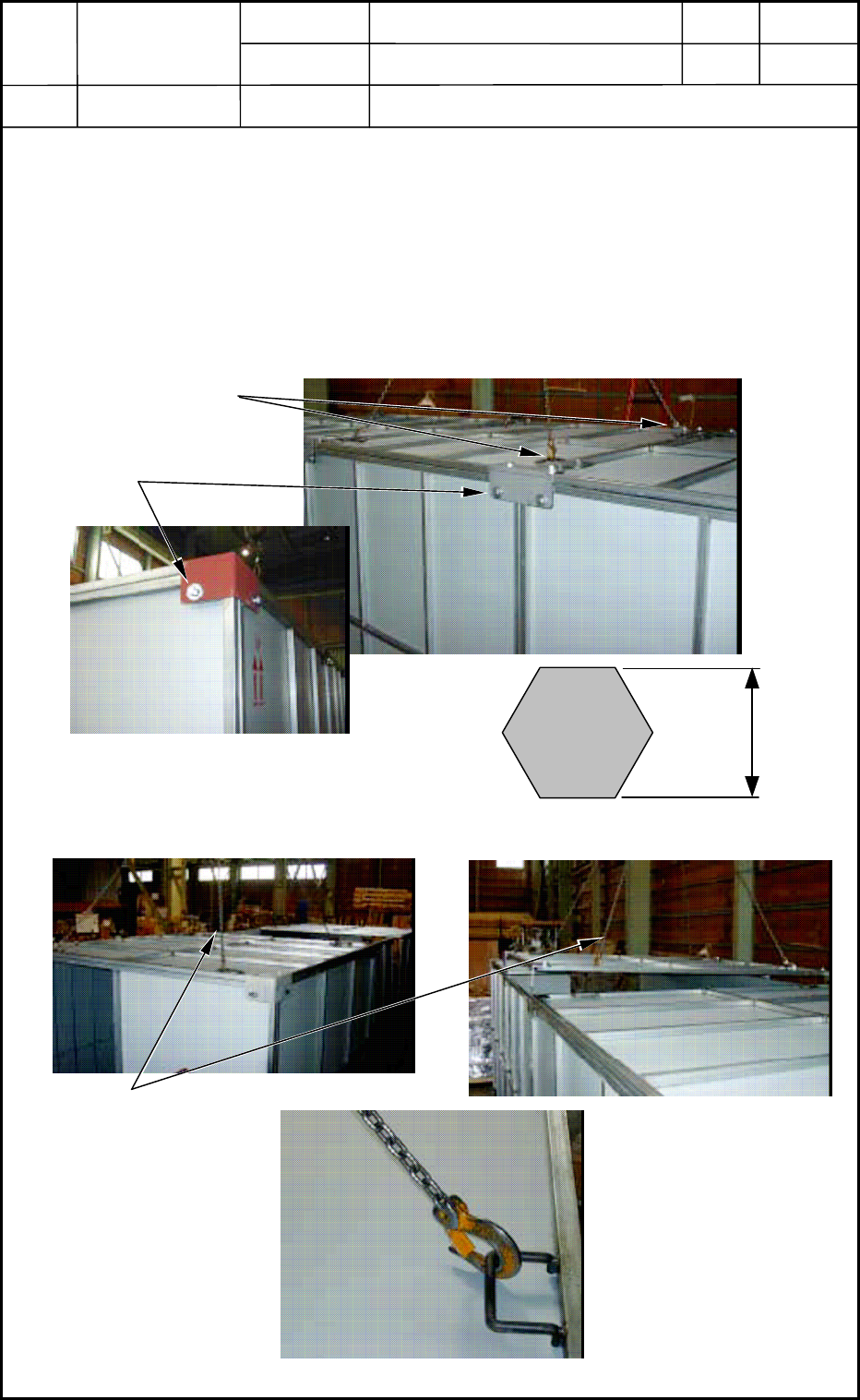
(1) To prevent the top panel from dropping, connect a chain or a wire with the anchor hook
of the panel to be detached.
(2) Remove twelve (12) bolts (M16) fastening the top panel. After that, connect chains or
wires with the anchor hooks (4 places) of the 2-divided top panel and lift the top panel to
detach.
(3) Follow the same procedure and lift the other top panel to detach.
Fig. R5
Fig. R6
18-11
0512-001
Chain or Wire
Anchor Hooks
Top Panel Mounting Bolts
20 mm
Panel Mounting Bolt M16
Chain Connected with
Anchor Hook
Device
Name
Chip Mounter
Block Name
Page No.
Unit Name
Revision
Model Item GXH-1
Chapter 18 Packaging
2. Packaging Procedure
2.2.2 Detachment of Side Panels
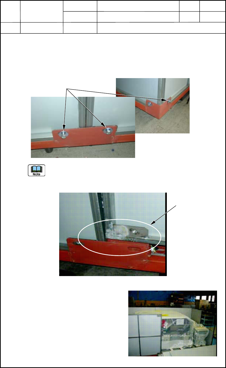
(1) Sixteen mounting bolts (M16) are used to fasten the side panels. Eight of them were
already removed to detach the top panels. Remove the remaining eight bolts from the
lower areas of the side panels.
Fig. R7
The side panels are inserted in the special grooves and self-standing. They do not fall
down after all of the mounting bolts are removed.
To detach a side panel, lift it upward as shown in Fig. R8.
Fig. R8
(2) Detach the right side panel as shown in
Fig. R9, then the left one.
(3) Detach the two side panels on the other
side.
Fig. R9
18-12
0512-001
Side Panel Mounting Bolts
Special Groove for
Self-Standing
Device
Name
Chip Mounter
Block Name
Page No.
Unit Name
Revision
Model Item GXH-1
Chapter 18 Packaging
2. Packaging Procedure
2.2.3 Detachment of End Panels
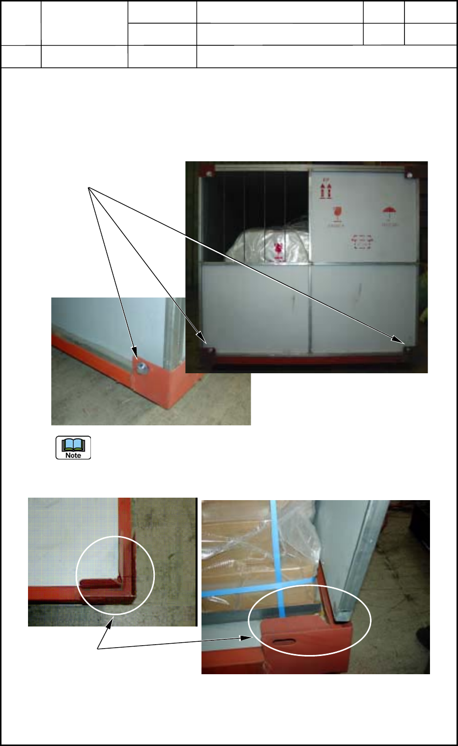
(1) Eight mounting bolts (M16) are used to fasten the end panels. Four of them located on
the upper area were already removed to detach the top panels. Remove the remaining
four bolts from the lower areas of the end panels.
Fig. R10
The end panels are inserted in the special grooves and self-standing. They do not fall
down after all of the mounting bolts are removed.
To detach an end panel, lift it upward as shown in Fig. R11.
Fig. R11
(2) Detach an end panel on the other side.
18-13
0512-001
End Panel Mounting Bolts
Special Groove for Self-Standing