SM-131-006.pdf - 第54页
Device Name Chip Mounter Block Name Page No. Unit Name Revision 0403-001 Model Item GXH-1 1. Leveling 1.1 Installation Position of Level Vials • The level vials must be installed on Areas "A", "D", &q…

0403-001 1-B
Device
Name
Chip Mounter
Block Name
Page No.
Unit Name
Revision
0403-001
Model ItemGXH-1
1. Leveling
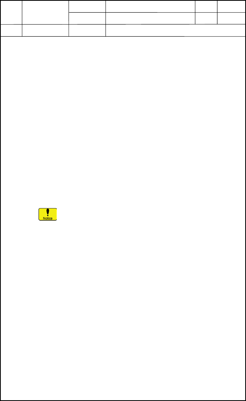
1.1 Installation Position of Level Vials
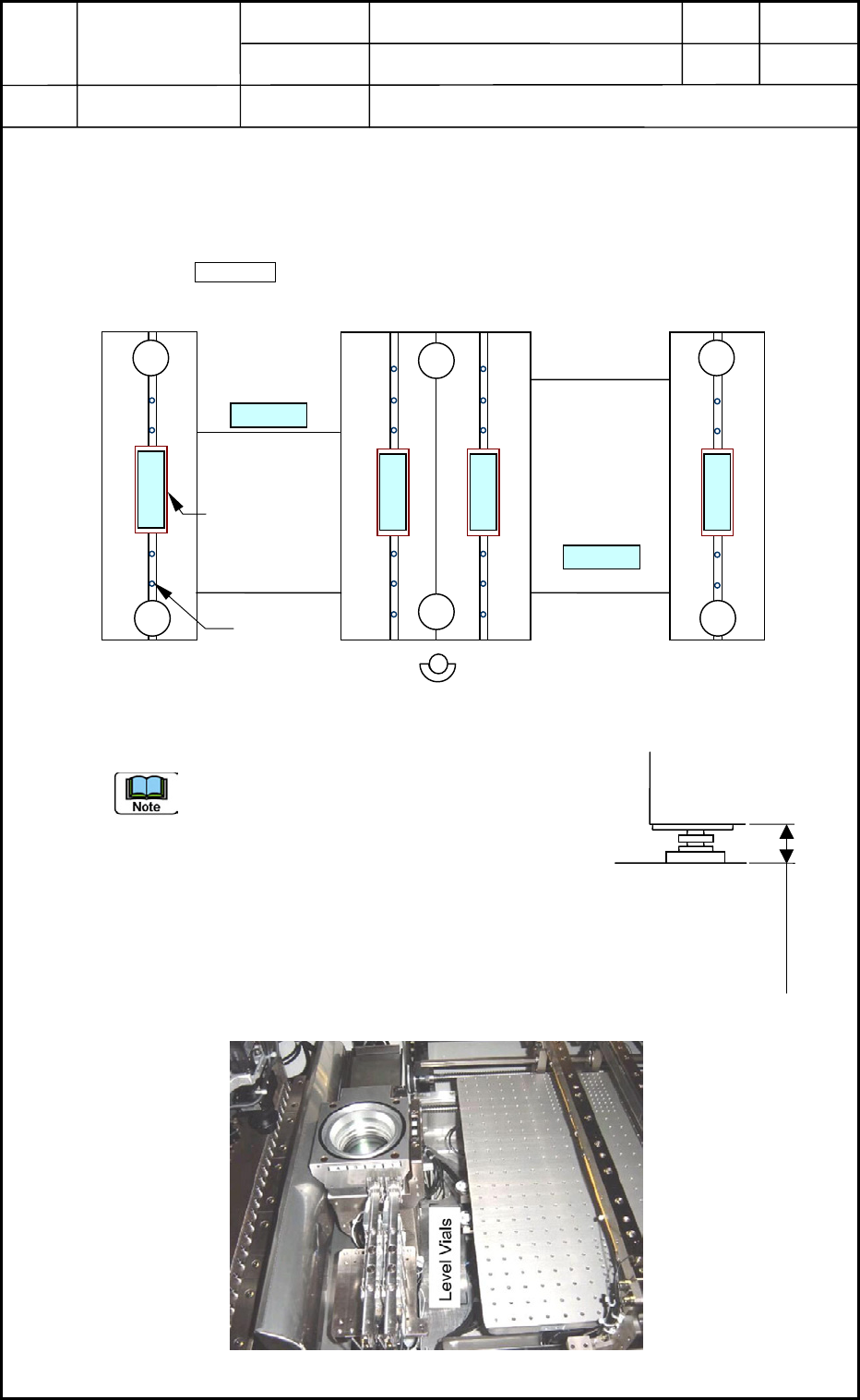
• The level vials must be installed on Areas "A", "D", "a", "b", "c", and "d" (6 places
in total). ( Areas)
• The pedestals must be mounted on Areas "1" through "6" (6 places in total).
Front Side
Fig. A1 Installation Position of Level Vials
(a) The jigs (flat plates) are required for Level
Vials a, b, c, and d because they are placed
on the linear guides.
(b) Confirm that the caps of the linear guides
are inserted adequately (0.1 to 0.2 mm) and
do not protrude.
(c) The target height (the distance between the
floor and the frame shown in Fig. A2) is
approximately 90 mm when the distance
between the floor and the conveyor transfer
plane is 905 mm.
Fig. A3 Installation Position of Level Vial D
A
D
5
6
2
1
3
4
bdc
a
Cap
Jig (Flat Plate)
Frame
Floor
Approx. 90 mm
Fig. A2 Distance between
Floor and Frame
Installation Procedure
1. Leveling
1-1
Device
Name
Chip Mounter
Block Name
Page No.
Unit Name
Revision
0403-001
Model ItemGXH-1
1.2 Leveling
• With the four pedestals (1 through 4) being mounted, adjust the X and Y directions.
(1) Adjust the pedestals for Level Vials a and b to detect that the machine is installed
horizontally in Direction Y.
(Target in Direction Y: within one graduation)
The jigs (flat plates) are required for the level vials because they are placed on the linear
guides.
Confirm that Level Vials c and d can also detect the horizontal installation of the
machine.
(2) Adjust the pedestals for Level Vials A and D to detect that the machine is installed
horizontally in Direction X.
Depending on outward warpage, the equal graduations can be allocated to both A and D.
(3) Lock four pedestals (1 through 4).
(4) Reconfirm that the machine is installed horizontally in both X and Y directions. (Level
Vials A, D, a, b, c, and d)
(Target in Direction Y: within one graduation)
• With the six pedestals (1 through 6) being mounted, adjust the X and Y directions.
(1) Lock Pedestals 5 and 6 and confirm that Level Vials A and D for Direction X and Level
Vials a, b, c, and d for Direction Y can detect the horizontal installation of the machine.
When Pedestals 5 and 6 are adjusted too high for the X-direction
adjustment, Pedestals 1 through 4 may be raised afloat.
Installation Procedure
1. Leveling
1-2