SM-131-006.pdf - 第58页
Device Name Chip Mounter Block Name Page No. Unit Name Revision Model Item GXH-1 • Clamping of Jig PCB (No Support Pins) Required Jig: Nozzle Height Check Jig (JG-0100) (160 × 80 mm, t = 2.3 to 2.6 m m) Note the PCB thic…
Device
Name
Chip Mounter
Block Name
Page No.
Unit Name
Revision
Model ItemGXH-1
2.2 Manual Offset
• Detach the feeder position indication cover on each stage beforehand.
2.2.1 Head Level Offset (Each Head)
(a) It is required to release the [STAGE READY] switches because this maintenance
work must be performed with the doors being opened.
(b) Confirm that the nozzle up/down axes are zeroed.
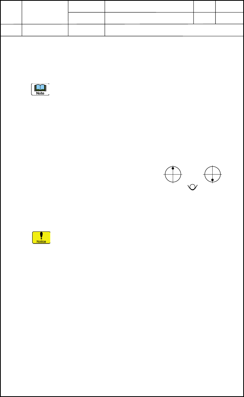
• Attachment of Master Nozzle (No. 1 Nozzle Position)
(1) Move the head to a position where the nozzle can easily be attached.
(1.1) Enter "1" in the "Nozzle No." text box for
"Designate nozzle". (Operation Sequence:
[MAINT] Button → [TEACHING]
Button → [NOZ LVL OFFSET] Button)
(1.2) Select the [Nozzle placement position
move] button and press the [START]
button.
(2) Attach the nozzle to the nozzle No. 1 position. (See Fig. A5.)
Be careful not to make the nozzle and your finger touch the linear
measure sensor section.
(3) After the master nozzle has been attached, perform a zeroing operation for the nozzle.
(3.1) Select one of the [Block 1], [Block 2], [Block 3] and [Block 4] buttons in the
"MOTOR" window. (Operation Sequence: [RETURN] Button → [DVC
CHECK] Button → [MOTOR] Button)
(3.2) Select the [DD] button.
(3.3) Select the [Sel axis] button and press the [START] button.
Origin Attachment
Position Position
Operator Side
Fig. A5 Nozzle Position
Heads
2. Installation Offset
1-4
0403-001
Device
Name
Chip Mounter
Block Name
Page No.
Unit Name
Revision
Model ItemGXH-1
• Clamping of Jig PCB (No Support Pins)
Required Jig: Nozzle Height Check Jig (JG-0100)
(160 × 80 mm, t = 2.3 to 2.6 mm)
Note the PCB thickness in the current pattern program.
(1) Zero the conveyor width as follows.
Open the "PRODUCT CHANGE" window and select the [L Cnvr], [Cnvr], and [R Cnvr]
buttons and press the [Zeroing] button to zero each conveyor. (Operation Sequence:
[SETUP] Button → [PROD. CHG.] Button)
Example: Selecting [L Cnvr] Button → Selecting [Zeroing] Button → Pressing
[START] Button
(2) Change the conveyor width as follows.
Enter "80" in the "Tgt Wd" text box and "0.8" in the "Clearance" text box, "200" in the
"Base Pos" text box in the "Cnvr Wd" group box of the "PRODUCT CHANGE" window.
Move the L conveyor, the conveyor, and the R Conveyor to the target positions.
Example: Selecting [L Cnvr] Button → Selecting [Desig Width] Button → Pressing
[START] Button
Conveyor Width Change Operation
• Open the "ADJUST" window. (Operation Sequence: [OPERATOR] Button
→ [MAINT.] Button → [DVC CHECK] Button → [ADJUST] Button)
Enter "80" for "Wd" and "200" for "Ofst" in relation with each item "Stg#1",
"Center", "Stg#2" in the "Suiting of width of conveyor (Start)" group box.
When each button in the "Suiting of width of conveyor (Start)" group box is
selected and the [START] button is pressed, the corresponding conveyor
width is changed.
• PCB clamping can also be performed by navigating through this window.
• After placing a PCB at the clamping position, set "BackUp Base" in the "Opn
mode" text box in the "P.C.B. transfer" group box.
Select the [Inp/Pos PCB] button and press the [START] button.
When the [START] button is pressed after the [Out PCB] button, the
clamping is released.
(3) Clamp the jig PCB.
(3.1) Put the jig PCB on the positioning center by hand.
(3.2) Use the "Output Chk" tab sheet to make the PCB clamped.
(3.3) Open the "Output Chk" tab sheet and select the [Block 5] button. (Operation
Sequence: "MAINT." Button → "DVC CHECK" Button → [INP/OUT] Button
→ "Output Chk" Tab Sheet)
(3.4) Select the [CNVRL] or the [CNVRR] button.
Select the [D4] button in the "Select Bit" group box.
[D4]: Z Clamp Cylinder Valve 1 (A) [NA] or [NC]
(3.5) Press the [ON] button in the "Control Sw" group box.
(3.6) [D5]: Z Clamp Cylinder Valve 1 (B) [NA] or [NC]
The clamping is completed.
Heads
2. Installation Offset
1-5
0403-001
Device
Name
Chip Mounter
Block Name
Page No.
Unit Name
Revision
Model ItemGXH-1
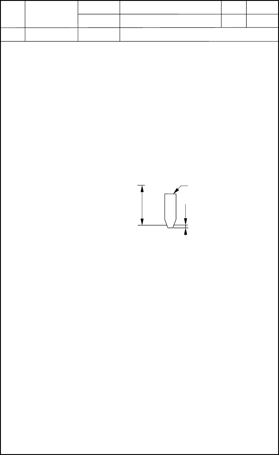
• Head Movement to Measuring Position
X = Origin Position, Y1 = -514 mm (#1 and #3 Heads)
514 mm (#2 and #4 Heads)
(1) Select one of the [Block 1], [Block 2], [Block 3] and [Block 4] buttons in the "MOTOR"
window. (Operation Sequence: [MAINT.] Button → [DVC CHECK] Button →
[MOTOR] Button)
(2) Select the [Y1] button.
Select the [Relative] button in the "Manual Axis action (start)" group box and enter the
amount of movement (travel).
(3) Select the [-] or the [+] button and press the [START] button.
• Measurement
When the head is moved to the measuring position, HL and NL are related as shown in Fig.
A6 at each origin position.
Measuring Method : Example: (a) Use a block gauge (32 mm) for the measurement.
(b) Move down the HL axis (basic stroke) by 24
mm and the NL axis by 8 mm and perform the
measurement.
Example of Data Entry : When the nozzle is located below the reference plane, a plus
value must be entered. Enter "-0.1 mm" for "Head Up/Down
Offset".
• Entry of Offset Data
Enter parameters in the "Head Up/Down" tab sheet and save the changes. (Operation
Sequence: [SUPV] Button → [EDIT] Button → [SYSTEM] Button → [EDIT] Button
entitled "Machine System" → "Head" Tab Sheet → "Head Up/Down" Tab Sheet)
Heads
2. Installation Offset
1-6
Fig. A6 Measurement of Head Level Offset
PCB Upper Surface Reference Point
Design Value of
Stroke
32
Master Nozzle
0.1
L1
Unit : mm
0403-001