SM-131-006.pdf - 第71页
Device Name Chip Mounter Block Name Page No. Unit Name Revision Model Item GXH-1 0406-001 Chapter 1 Installation Procedure 1-18
Device
Name
Chip Mounter
Block Name
Page No.
Unit Name
Revision
Model ItemGXH-1
3. In-Line
3.1 Machine Delivery
Do not disconnect the conveyor on the machine reference side and the fixtures
until the level, height, and parallelism adjustments are completed.
(1) Detach the fixtures before supplying power to the machine.
(Two Flanged Bolts M5L10 for one place)
Perform the same detachment for the input and output sides.
3.2 Machine Transfer
Perform the conveyor width change operation before shutting down the power supply.
(1) Open the "ADJUST" window. (Operation Sequence: [OPERATOR] Button →
[MAINT] Button → [DVC CHECK] Button → [ADJUST] Button)
Enter "460" for "Wd" and "10" for "Ofst" in relation with each items "Stg #1" and
"Stg#2" in the "Suiting of width of conveyor (Start)" group box.
When each button in the "Suiting of width of conveyor (Start)" group box is selected
and the [START] button is pressed, the conveyor width change function is activated.
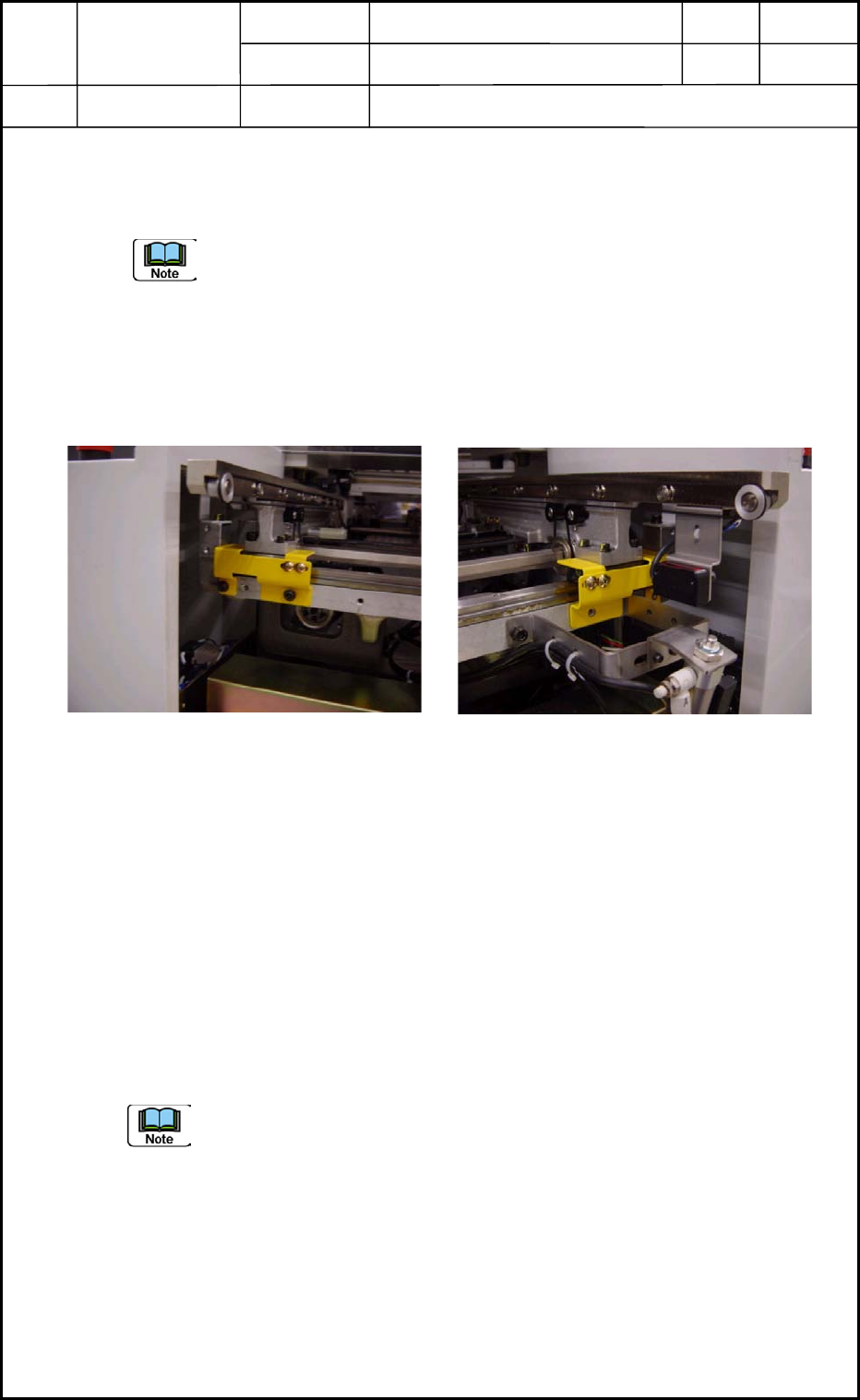
(2) Attach the fixtures to the reference rails sides at both ends of the conveyor.
• Perform the attachment while the power switch is kept ON.
Check for looseness and play of the fixed conveyor section.
(3) After the attachment of the fixtures are completed, shut down the power supply to the
machine.
Fig. 10 Conveyor on Machine
Reference Side
Fig. A9 Conveyor on Input Side
0406-001
Chapter 1 Installation Procedure
3. In-Line
1-17

Device
Name
Chip Mounter
Block Name
Page No.
Unit Name
Revision
Model ItemGXH-1
0406-001
Chapter 1 Installation Procedure
1-18

Chapter 2
Up-/Down-Grading of Software Version
This chapter describes how to up-grade or down-grade the
software version.
• Procedure for Version Up-Grading
• Procedure for Version Down-Grading
0406-001 2-A