SM-131-006.pdf - 第85页
0406-001 4- B

Chapter 4
Beam Section
This chapter describes how to change and adjust the beam
section.
• Replacement of X-Axis Motor Stator and Rotor
• Replacement of Y-Axis Motor Stator and Rotor
• Replacement of Servoamplifier
• Replacement and Adjustment of X-Axis Encoder
• Replacement and Adjustment of Y-Axis Encoder
• Replacement of Linear Scale
0406-001 4-A

0406-001 4-B
Device
Name
Chip Mounter
Block Name
Page No.
Unit Name
Revision
Model ItemGXH-1
Chapter 4 Beam Section
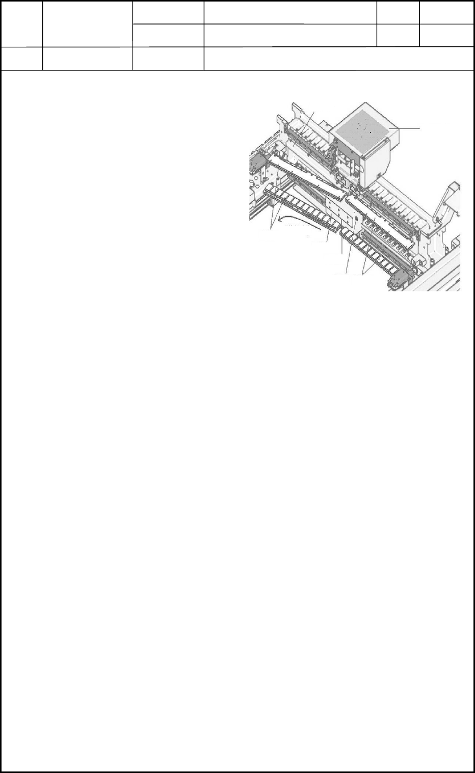
1. Replacement of X-Axis Motor Stator and Rotor
1.1 Detachment of X-Axis Motor Stator
(1) Shut down the power to the machine.
(2) Move the head unit (rotor) to the
rear side of the machine.
(3) Detach the X-axis linear scale
together with the block.
(4) Detach the protective cover.
(5) Attach the stator carrier jig to
Stator 1.
(6) Remove the setscrews of Stator 1.
(7) Detach Stator 1 in the pullout
direction shown in Fig. D1.
(8) Move the rotor outside of the
machine.
(9) Attach the stator carrier jig and
detach Stator 2
1.2 Detachment of X-Axis Motor Rotor
(1) Detach Stator 1.
(2) Detach the head unit.
Refer to "1. Replacement of Head Unit" in Chapter 5 for details.
(3) Open the head wiring section and pull out the power connector of the rotor.
Refer to "1. Replacement of Head Unit" in Chapter 5 for details.
(4) Move the head mounting block to the area of Stator 1.
(5) Loosen the setscrews and detach the rotor from the mounting block.
Protective Cover
Head Wiring
Section
Beam A
Stator 1
Stator 2
Pullout
Direction
Rotor
Pin Pushing Face
Power Line
Fig. D1 X-Axis Motor Section
0406-001
4-1