SM-131-006.pdf - 第88页
Device Name Chip Mounter Block Name Page No. Unit Name Y-Axis Motor Revision Model Item GXH-1 Chapter 4 Beam Section 2. Replacement of Y-Axis Motor Stator and Rotor 2.1 Detachment of Y-Axis Motor Stators • Detach Stator …
Device
Name
Chip Mounter
Block Name
Page No.
Unit Name
Revision
Model ItemGXH-1
Chapter 4 Beam Section
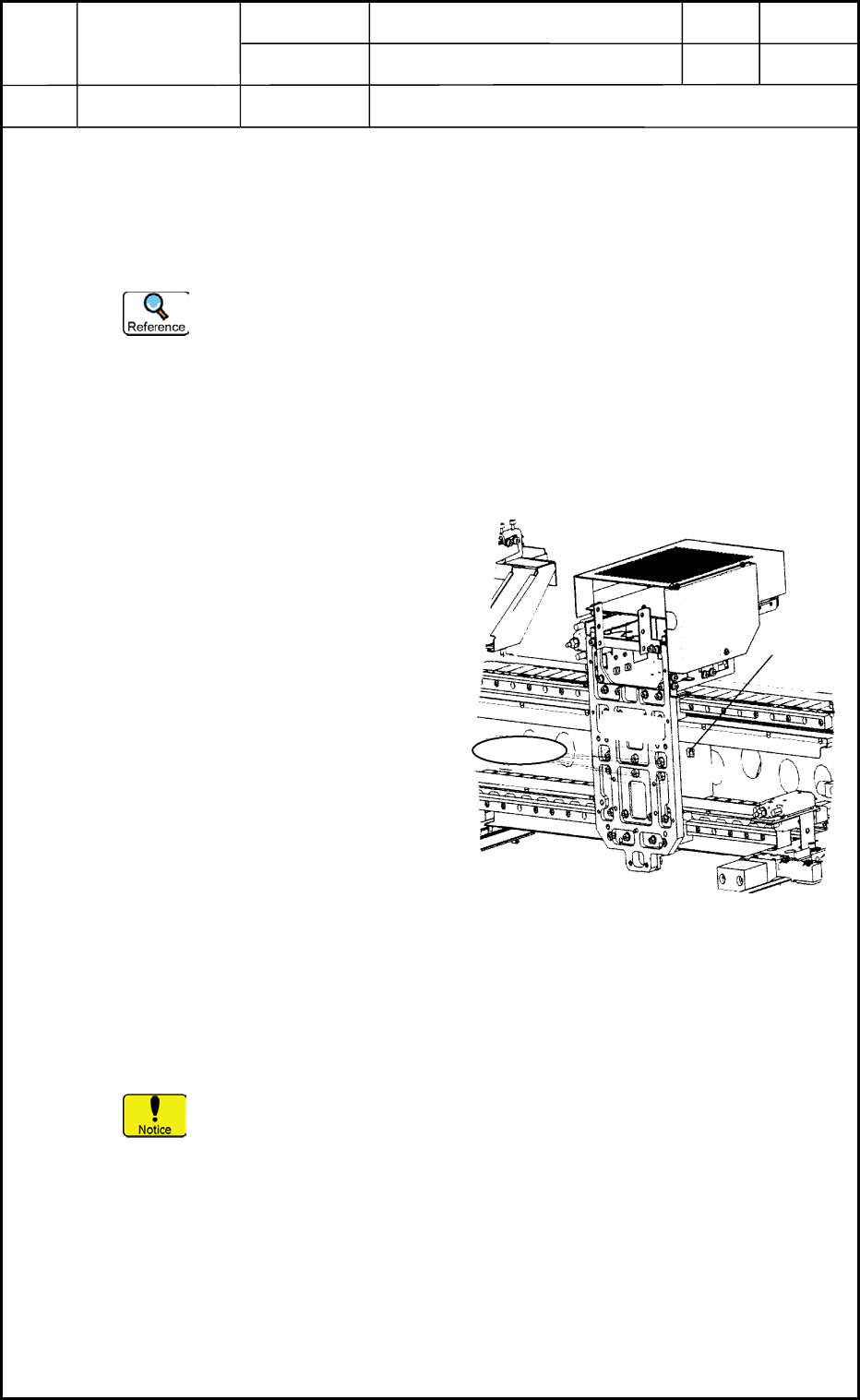
1. Replacement of X-Axis Motor Stator and Rotor
1.3 Attachment of X-Axis Motor Stator and Rotor
(1) Push Stator 2 against the stator positioning pin and tighten the setscrews to fasten the
stator securely.
(2) Detach the stator carrier jig.
(3) Attach the rotor to the mounting block in the area of Stator 1.
Positioning of Rotor
(3.1) Position the rotor such that the power line of the motor can be located on
the top of the rotor. (cf. Fig. D2)
(3.2) Attach the rotor to the head mounting block by temporarily tightening the
setscrews.
(3.3) Push the rotor against the positioning pin of the mounting block and
tighten the setscrews securely.
(4) Move the rotor toward Stator 2.
(5) Attach Stator 1 from the opposite side
of the pullout direction shown in
Fig. D2.
(6) Push Stator 1 against Stator 2 and
fasten it by tightening the setscrews
securely.
(7) Attach the stator carrier jig of Stator 1.
(8) Check the clearance between the stator
and the rotor.
Specified Value: 0.7±0.2 mm
(9) Connect the power connector of the
rotor to the wiring section.
Refer to "1. Replacement of Head
Unit" in Chapter 5 for details.
(10) Attach the protective cover and the
X-axis linear scale block.
(11) Check the position of the linear scale and the light intensity of the X-axis encoder.
Refer to "6. Replace of Linear Scale" for details.
(12) Attach the head unit.
Refer to "1. Replacement of Head Unit" in Chapter 5 for details.
It is recommended that new setscrews should be used for the stators.
1.4 Adjustment and Teaching Operations Required after Work
The offsets must be adjusted generally.
Refer to "6. Adjustment of Offsets" in Chapter 5 for details.
Rear Side
Outside
Head
Wiring
Motor Power
Mounting
Block
Setscrews (6 pcs.)
Rotor
Fig. D2 Attachment of Rotor
0406-001
4-2
Device
Name
Chip Mounter
Block Name
Page No.
Unit Name
Y-Axis Motor
Revision
Model ItemGXH-1
Chapter 4 Beam Section
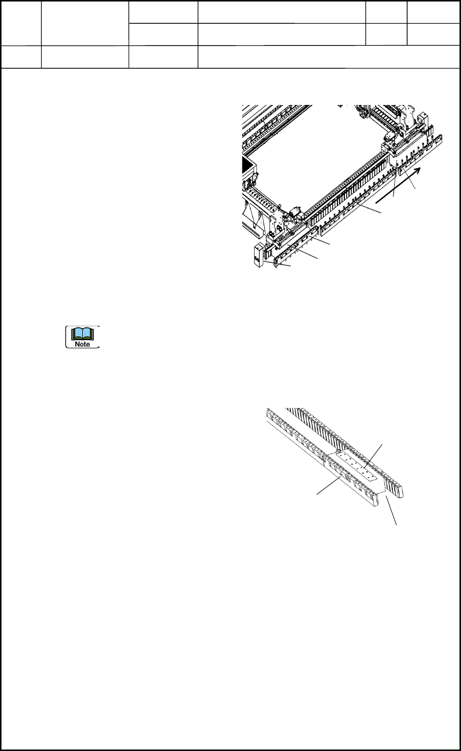
2. Replacement of Y-Axis Motor Stator and Rotor
2.1 Detachment of Y-Axis Motor Stators
• Detach Stator 1, Stator 2, and Stator
3 in this order as shown in Fig. D3.
Keep this order because the
positional reference pins of the
stators are located on the front side
of the device.
(1) Move the rotor toward Stator 2
beforehand.
(2) Attach the stator carrier jig to Stator 1.
(3) Remove the setscrews.
(4) Detach Stator 1 by slowly pulling it
out in the pullout direction shown in
Fig. D3.
(5) Follow the same procedure to detach
Stators 2 and 3.
Before the stators for the Y1 axis are detached, it is required to detach the rear
operation monitor, the ceiling pillar, the mechanical stopper, and the robot cable, etc.
2.2 Detachment of Y-Axis Motor Rotors
• Be sure to detach the rear rotor first
and then the front rotor.
(1) Detach the beam first.
(Including the robot cable, etc.)
(2) Move the rotor toward Stator 2.
(3) Detach Stator 1.
(4) Move the rotor to the area of Stator 1.
(5) Loosen the setscrews of the rotor and
detach the rotor.
Y1 Axis
Rear Side
Front Side
Y2 Axis
Pullout
Direction
Stator 1
Rotor
Stator 2
Stator 3
Rotor
Reference Pin
Fig. D3
Right Side
0406-001
4-3
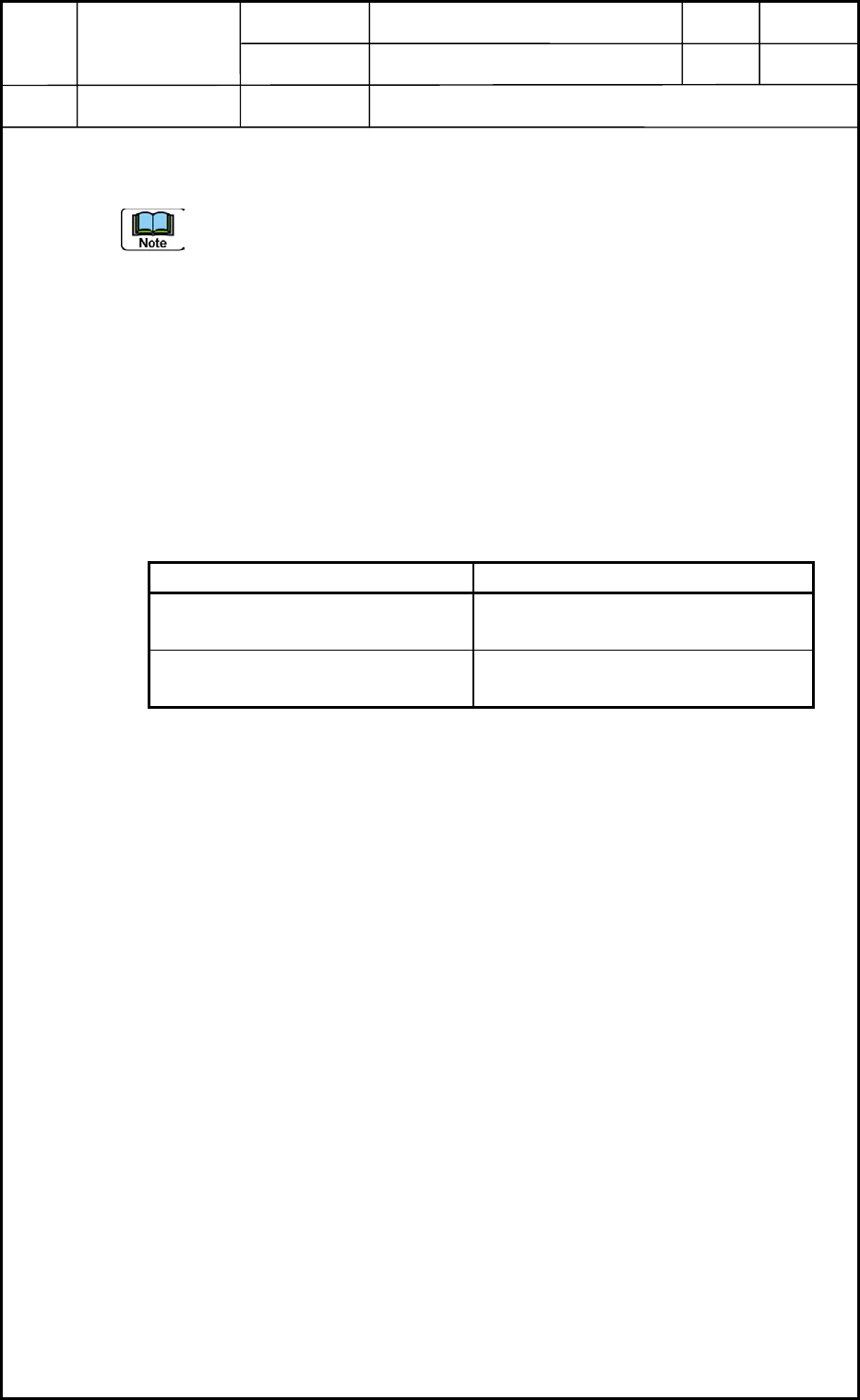
Stator
Rotor
Clearance
Fig. D4
Device
Name
Chip Mounter
Block Name
Page No.
Unit Name
Y-Axis Motor
Revision
Model ItemGXH-1
Chapter 4 Beam Section
2. Replacement of Y-Axis Motor Stator and Rotor
2.3 Attachment of Y-Axis Motor Stators and Rotors
(1) Attach Stator 3.
Positioning Method: Push Direction X against the reference pin and Direction Y
against the rear side.
(2) Attach Stator 2.
Be sure to push Stator 2 until it touches Stator 3.
(3) Attach the front rotor to the fixing block in the area of Stator 1 and move it toward the
front side.
(4) Attach the rear rotor to the fixing block in the area of Stator 1 and move it toward the
front side.
(5) Mount Stator 1.
Be sure to push Stator 1 until it touches Stator 2.
(6) Attach the other parts and units that were detached.
Specified Values Table D1
Name Specified Values
Pushing Distance (Clearance) for
Positioning
The thickness gauge of 0.01 mm
should not pass through the clearance.
Clearance between Stator and Rotor
(Fig. D4)
0.7±0.2 mm (all over the area)
2.4 Adjustment and Teaching Operations Required after
Replacement
The offsets must be adjusted generally.
Refer to "6. Adjustment of Offsets" in Chapter 5 for details.
0406-001
4-4