JP-001-001e.pdf - 第5页
1005-001 目 次 CONTENTS テープフィーダ調整治具 T ape Feeder Ajusting Jig JG-0209, 0209E, 0209J JG-0209, 0209E, 0209J Fig. B 治具本体部 JIG MAIN BODY SECTION Fig. B-1 ベース部 Base Sectio n Fig. B-2 XY テーブル部 XY T able Section Fig. B-3 フィーダセット部…
1005-001
2
USING YOUR EXPLODED ILLUSTRATION
This Exploded Illustration shows the information about the parts of Tape Feeder
Ajusting Jig JG-0209, 0209E, 0209J for GXH Series and is made for Parts Ordering.
You must not replace a part with a new one according to only the information of this
Exploded Illustration.
1. Inquiring
For identification of each part, numbers are placed on illustration pages. These
numbers (Key No.) again appear in the far left column of the part table joined up
with the illustration.
The number shown in the Q’ty column of the part table represents the quantity of
certain part used in the equipment. In case of unit assembly, however, the number
represents the quantity of certain part contained in single unit.
2. Parts Ordering
For ordering parts, some parts might not be supplied as a single item, due to the
constitution of such parts.
When ordering parts, be sure to inform us of the following details:
Model Type
Serial No.
Fig. No.
Key No.
PART No.
PART NAME
Quantity
[Example]
3. Miscellaneous
This Exploded Illustration is subject to change without prior notice.
All rights reserved. No part of this work covered by the copyrights hereon may be
reproduced or copied without written permission of the publisher.
'' NOTE '' is used to show the notice that is not directly related to safety.
Some of the parts shown in the Exploded Illustration could fall into the scope of your
government’s regulations on strategic products. In that case, anybody who intend to
export the product should acquire due authorization.
JG-0209
Model Type
123456S 7890
Serial No.
Key No.106
Key No.
6301741154
PART No.
Q'ty
1
Fig. No.
Fig. B-1
PART NAME
CLAMP
1005-001
目 次
CONTENTS
テープフィーダ調整治具
Tape Feeder Ajusting Jig
JG-0209, 0209E, 0209J JG-0209, 0209E, 0209J
Fig. B
治具本体部
JIG MAIN BODY SECTION
Fig. B-1
ベース部
Base Sectio
n
Fig. B-2 XY
テーブル部
XY Table Section
Fig. B-3
フィーダセット部
Feeder Set Section
Fig. B-4
フィーダクランプ部
Feeder Clump Section
Fig. B-5
ケーブル
Cable
Fig. C
電装ボックス部
ELECTRICAL BOX SECTIO
N
Fig. C-1
ベース部
Base Section
Fig. C-2
電装ボックス部
Electrical Box Section
Fig. C-3
ケーブル
Cable
Fig. C-4
電源回路図
Power Supply Circuit Diagram
3
CONT-1
1005-001
4
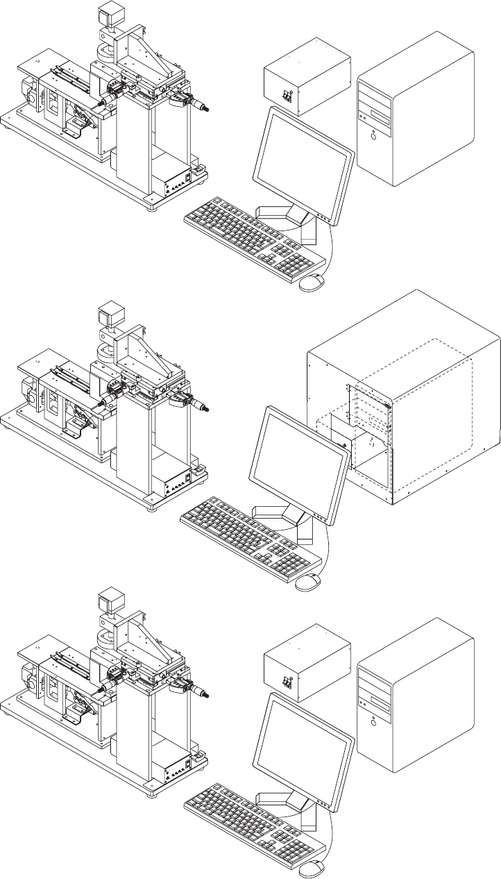
JG-0209E
JG-0209
JG-0209J
テープフィーダ調整治具
TAPE FEEDER AJUSTING JIG
JG-0209, 0209E, 0209J JG-0209, 0209E, 0209J