EPL6127110_YS12PF_Ope_E.pdf - 第43页
1-6 1 Part names and functions 3.1 Component pick-and-place head 3.1.1 5-in-line multi-head assembly T he 5-in-line multi-head assembly has 5 heads arranged in a row to pick up and place components. Head numbers are desi…
1-5
1
Part names and functions
3. Head assembly
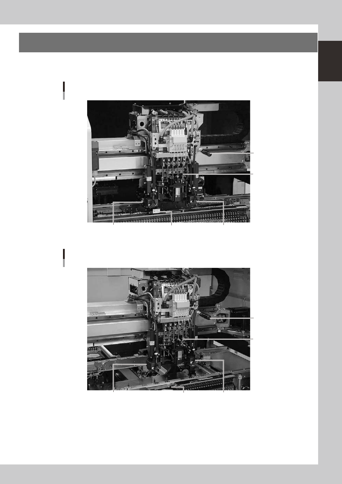
The head assembly is mounted on the XY arms and moves to pick up and place components. The following
sections describe the head assembly configurations and nozzle types.
Head assembly
YS12P
Fiducial camera lighting unit (option) Scan camera Fiducial camera lighting unit
5-in-line multi-head
Handle for moving
head assembly
23115-L6-00
Head assembly
YS12F
Fiducial camera lighting unit (option) Multi-vision camera Fiducial camera lighting unit
5-in-line multi-head
Handle for moving
head assembly
23115-L7-00
1-6
1
Part names and functions
3.1 Component pick-and-place head
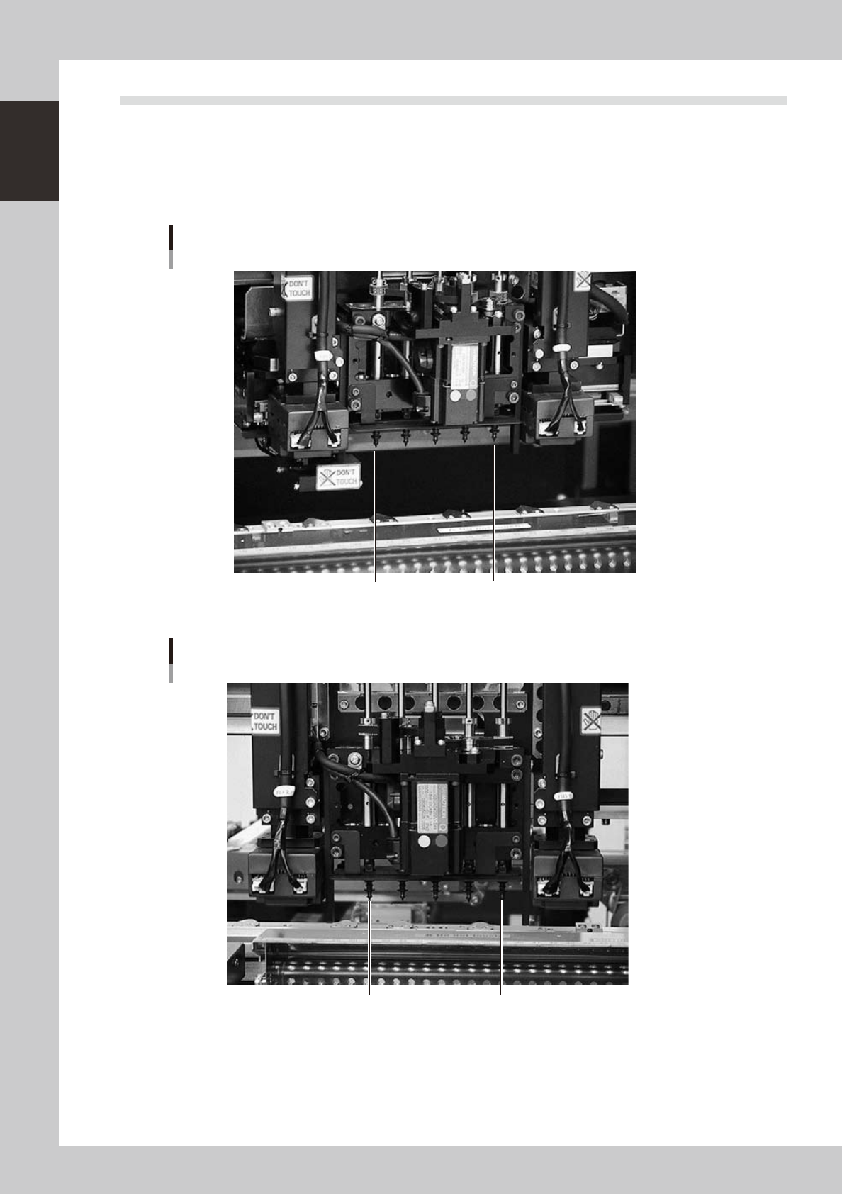
3.1.1 5-in-line multi-head assembly
The 5-in-line multi-head assembly has 5 heads arranged in a row to pick up and place components. Head
numbers are designated from 1 to 5, from the right as viewed from the front of the machine. The spacing of
adjacent nozzles attached to the head assembly is 24mm.
Head 5
Head 1
5-in-line multi-head assembly
YS12P
23105-L6-00
Head 5
Head 1
5-in-line multi-head assembly
YS12F
23105-L7-00
1-7
1
Part names and functions
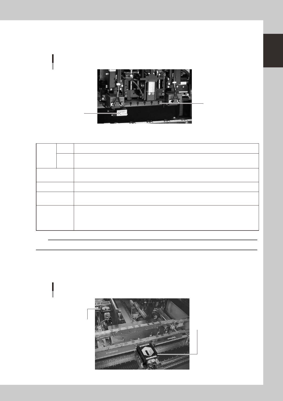
3.1.2 Scan camera (YS12P)
This scan camera moves right and left to recognize components while the head assembly moves to a
component mounting position after component pickup. This camera also has a side-view function as standard.
Scan camera
YS12P
Nozzle
Scan camera
23106-L6-00
n
Side-view function (Scan camera: YS12P only)
Pickup
error
detection
function
Normal
mode
Detects component pickup errors to prevent "no placement errors".
Normal mode operates even when nozzles are changed after nozzle cleaning, etc.
Detail
mode
Detects component pickup errors to prevent "no placement errors".
Checks for abnormal component pickups such as tilted, vertical or horizontal pickups based on the component
thickness tolerance set by the users.
Dirty nozzle sensing
function
If the side-view function shows "no component" even when another camera shows "component present", the
machine determines that the nozzle tip is "dirty" and a warning message appears. This serves as an accurate
guide for nozzle cleaning periods.
Component discard
skip
This function skips the discard operation when the side-view function shows "no component". This eliminates
unneeded operation when no component was picked up and prevents a loss of cycle time during production.
Remaining
component check
function
This detects whether a component still remains in the nozzle tip after components were mounted or discarded.
Inverted component
check function
In the recognition process after a component is picked up by a nozzle, this function checks if the front and back
sides of the component are inverted. It also simultaneously checks if that component size fits within the angle-
of-view of the side-view function.
An error message appears if recognition shows the component front and back sides are inverted or that
component will not fit within the angle-of-view. This function does not work for components that have leads on
the upper half of the body or have no leads on the side of the body.
n
NOTE
Refer to "Programming Manual" for side-view function parameter settings.
3.1.3 Multi-vision camera
This is a component recognition camera installed as standard on the front side of the YS12F.
This camera can also be added to the rear side as an option. (YS12P, YS12F)
Multi-vision camera
YS12F, YS12P
Rear multi-vision camera
(option)
Front multi-vision camera
(installed as standard in YS12F,
but not in YS12P)
23120-L7-00