EPL6127110_YS12PF_Ope_E.pdf - 第49页
1-12 1 Part names and functions 4. Component supply section The feeder setup section is equipped with feeder plates for installing feeders such as tape feeders, and power supply connectors and air connectors for driving …
1-11
1
Part names and functions
16
32
17
20
21
22
23
24
25
26
27
28
29
30
18
31
19
15
13
14
11
12
9
10
5
6
7
8
1
2
3
4
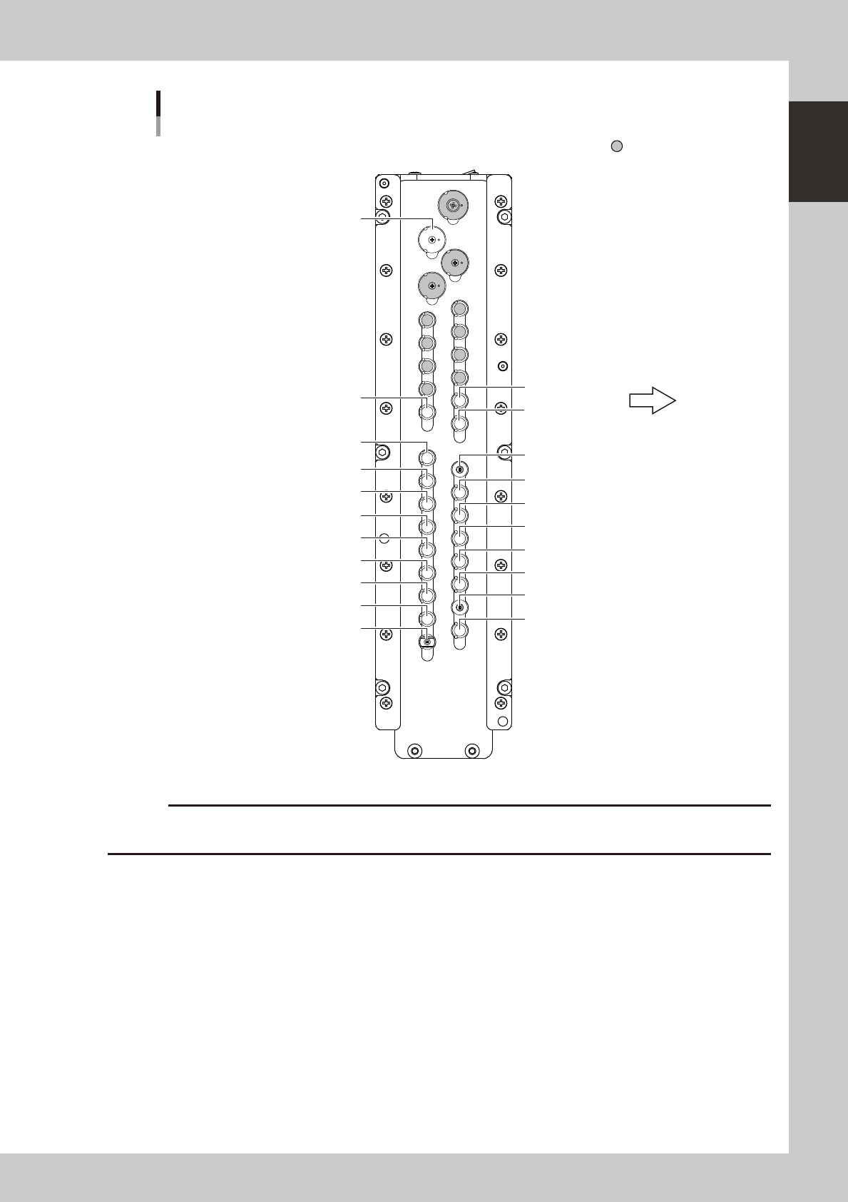
Nozzle station
Narrow adjacent type
H2
TYPE318A
H1
TYPE313A
H1
TYPE312A
H1
TYPE311A
H2
TYPE315A
H2
TYPE311A
H3
TYPE314A
H3
TYPE311A
H4
TYPE314A
H4
TYPE311A
H5
TYPE315A
H5
TYPE311A
H2
TYPE313A
H2
TYPE312A
H3
TYPE313A
H3
TYPE312A
H4
TYPE313A
H4
TYPE312A
H5
TYPE313A
H5
TYPE312A
Custom nozzle pockets
Front of machine
H1
TYPE314A
23112-L6-10
c
restrictions on the size of components suitable for those nozzles.
1-12
1
Part names and functions
4. Component supply section
The feeder setup section is equipped with feeder plates for installing feeders such as tape feeders, and
power supply connectors and air connectors for driving optional units. An auto tray changer (ATS15) can
also be installed on the rear of the YS12F as an option.
4.1 Supplying components from feeder plates
Tape feeders and stick feeders are installed on the feeder plate(s), and operate by electric power supplied from
the mounter.
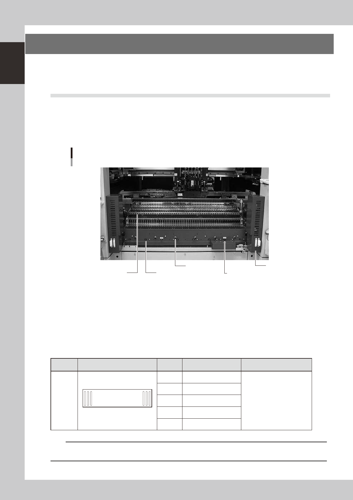
4.1.1 YS12P
The YS12P has only one 60-feeder plate fixed on the front side of the machine.
YS12P feeder plate section
Fixed 60-feeder plate
Safety cover
Air connector
Power supply connector
Power supply connector (for dump station)
60-feeder plate
23108-L6-00
Power supply connector
When using optional units such as stick feeders, plug the power cord into these connectors.
Air connector
Use these air connectors when using an optional device such as an air blow gun. Connect the air tube (outer diameter
4mm) to supply compressed air to the optional device from the mounter.
n
Head No. and feeder set No.
Some feeders cannot be reached by a head depending on the head assembly configuration and X-axis movement range.
The tables below show feeder set numbers that can be accessed by each head of the machine.
Type Layout Head No. Accessible feeder set No.
Number of feeders than can be
attached
Front
60-feeder
plate
(fixed)
1 60
1 10 to 60
59 when 8mm feeders are used
2 8 to 58
3 6 to 56
4 4 to 54
5 2 to 52
n
NOTE
Accessible feeder positions may differ from the above when the Feeder Definition parameter in component
information is set to "Teach" or "Relative".
1-13
1
Part names and functions
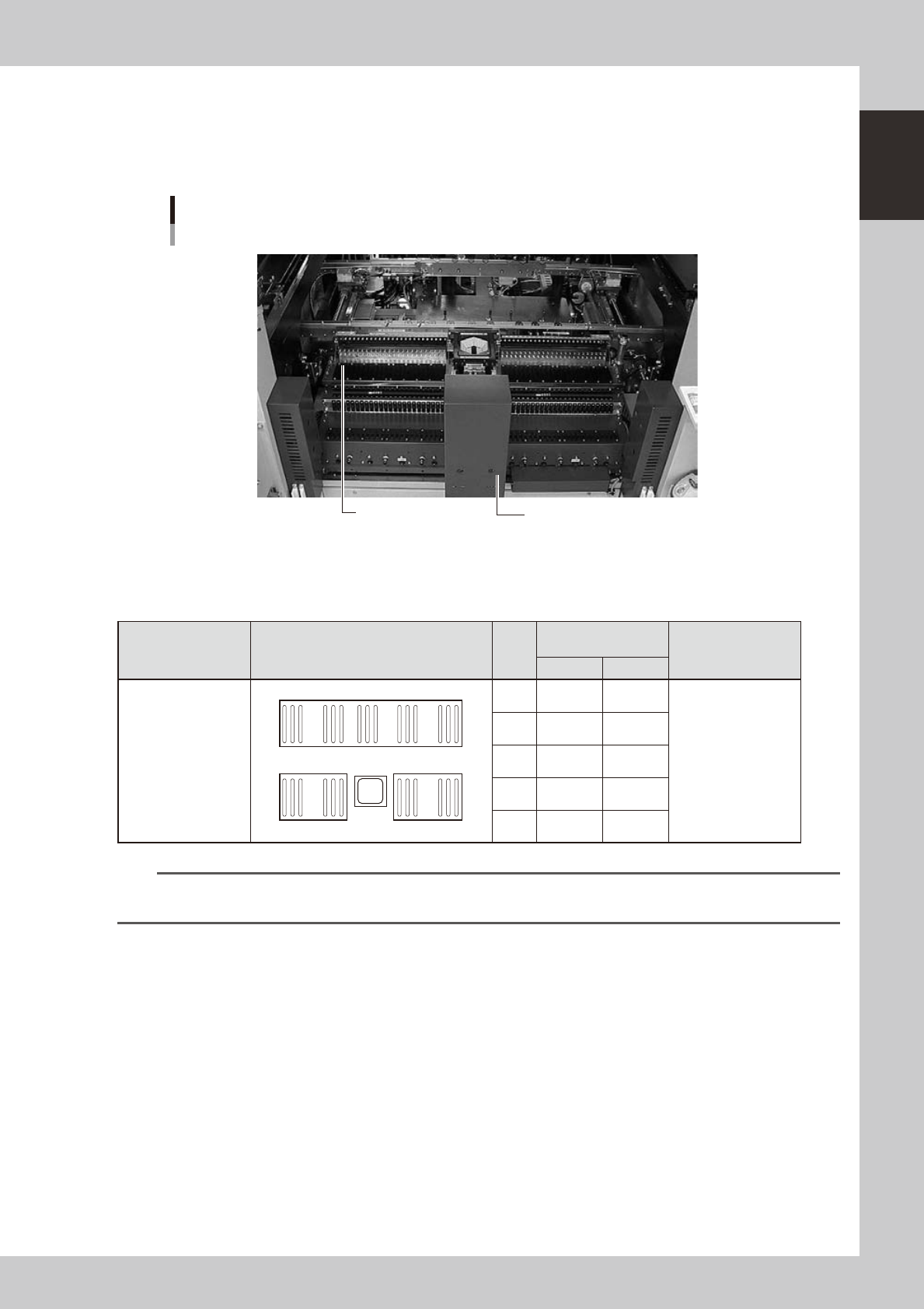
4.1.2 YS12F
The YS12F has two 24-feeder plates (fixed feeder plates or feeder exchange carriages) on the front side and one
60-feeder plate fixed on the rear side of the machine. If an ATS15 is installed on the rear side, the 60-feeder
plate is demounted.
YS12F feeder plate section
24-feeder plates fixed on front side
Safety cover
24-feeder plate
23108-L7-00
n
Head No. and feeder set No.
Some feeders cannot be reached by a head depending on the head assembly configuration and X-axis movement range.
The tables below show feeder set numbers that can be accessed by each head of the machine.
Type Layout
Head
No.
Accessible feeder set
No.
Number of feeders
than can be attached
Front Rear
Front 24-feeder plate
(fixed) × 2
(Fixed feeder plates
or feeder exchange
carriages)
Rear 60-feeder plate
(fixed)
1
24
25
48
160
101
1 10 to 48 101 to 151
Front:47
Rear:59
(When 8mm feeders
are used)
2 8 to 46 103 to 153
3 6 to 44 105 to 155
4 4 to 42 107 to 157
5 2 to 40 109 to 159
n
NOTE
Accessible feeder positions may differ from the above when the Feeder Definition parameter in component
information is set to "Teach" or "Relative".