EPL6127110_YS12PF_Ope_E.pdf - 第51页
1-14 1 Part names and functions 4.1.2 Feeder exchange carriage T he feeder exchange carriage allows feeder setup in ad vance for the next production boards. T he feeders on the feeder exchange carriage can be c hanged at…
1-13
1
Part names and functions
4.1.2 YS12F
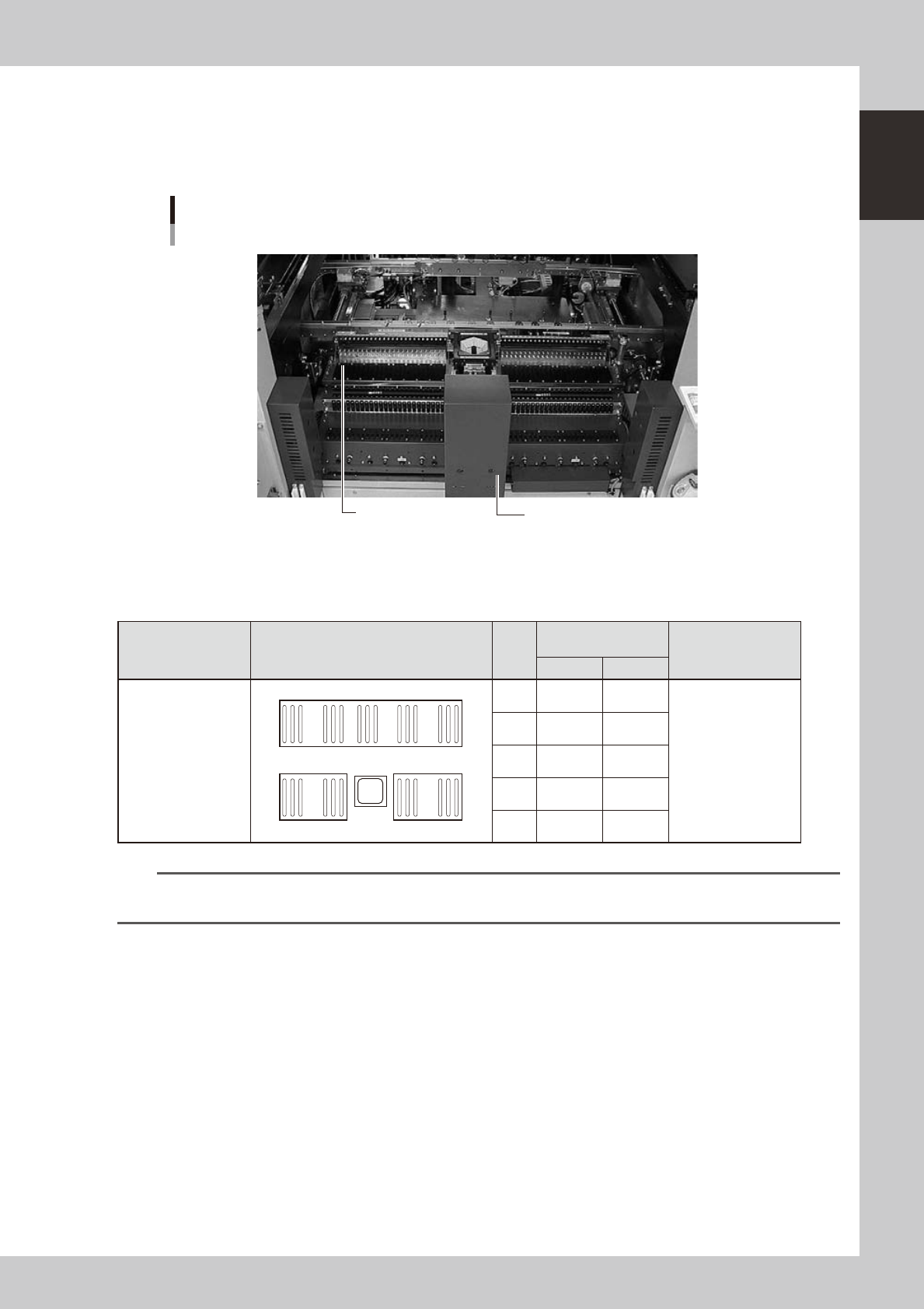
The YS12F has two 24-feeder plates (fixed feeder plates or feeder exchange carriages) on the front side and one
60-feeder plate fixed on the rear side of the machine. If an ATS15 is installed on the rear side, the 60-feeder
plate is demounted.
YS12F feeder plate section
24-feeder plates fixed on front side
Safety cover
24-feeder plate
23108-L7-00
n
Head No. and feeder set No.
Some feeders cannot be reached by a head depending on the head assembly configuration and X-axis movement range.
The tables below show feeder set numbers that can be accessed by each head of the machine.
Type Layout
Head
No.
Accessible feeder set
No.
Number of feeders
than can be attached
Front Rear
Front 24-feeder plate
(fixed) × 2
(Fixed feeder plates
or feeder exchange
carriages)
Rear 60-feeder plate
(fixed)
1
24
25
48
160
101
1 10 to 48 101 to 151
Front:47
Rear:59
(When 8mm feeders
are used)
2 8 to 46 103 to 153
3 6 to 44 105 to 155
4 4 to 42 107 to 157
5 2 to 40 109 to 159
n
NOTE
Accessible feeder positions may differ from the above when the Feeder Definition parameter in component
information is set to "Teach" or "Relative".
1-14
1
Part names and functions
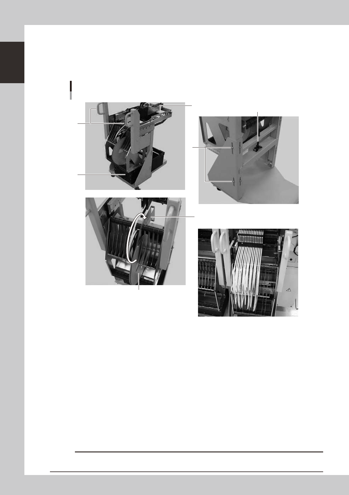
4.1.2 Feeder exchange carriage
The feeder exchange carriage allows feeder setup in advance for the next production boards. The feeders on
the feeder exchange carriage can be changed at one time.
n
Feeder exchange carriage
External view of feeder exchange carriage
1
2
4
6
5
3
Placing 7-inch reels continuously
A tape reel larger than 7 inches
23118-L7-00
1. Handle
Use this handle to move and position the feeder exchange carriage.
2. Feeder plate
Up to 24 SS feeders (8mm) can be installed on this feeder plate.
3. Vertical clamp bolts
If necessary to adjust the feeder plate height, loosen these bolts and change their clamping positions. (8 places)
4. Empty tape dump box (option)
This box is for catching empty tape after components have been picked up.
5. Height adjustment bolt
After loosening the vertical clamp bolts, turn this bolt to adjust the feeder plate height.
6. Reel holder
Each reel holder holds one tape reel (7 inches) for 8mm tape feeders.
When using a tape reel larger than 7 inches, raise this reel holder as shown above.
c
above.
1-15
1
Part names and functions
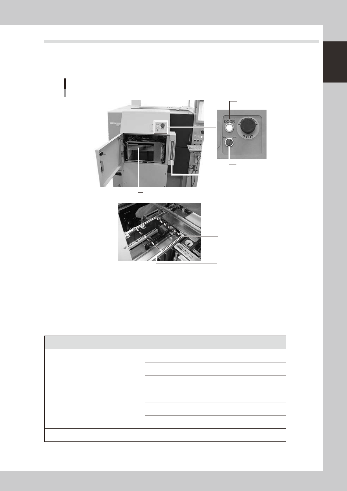
4.2 Supplying components from tray changer (ATS15)
Major part names and their functions of the tray changer (ATS15) are explained below.
4.2.1 ATS15 main unit
Tray changer main unit
ATS15
Pallet indicator
Guide rail
Pallet clamp position (work position)
Door switch
Door indicator
Pallet (Up to 15 pallets can be stored at 12.5mm pitch.)
23110-L7-00
Door switch
Setting this switch to "OPEN" unlocks the door and the DOOR indicator turns off.
Pallet indicator
The indicator lamps for the pallet No. set in the parts information are lit up. When the tray components on a pallet are
used up, the indicator lamp for that pallet No. flashes (see below). After setting new a pallet in the ATS15, press the
flashing indicator button to reset it.
n
Pallet indicator lighting pattern
Pallet condition Component condition Indicator status
One component type on one pallet
Components have been supplied. ON
Used up all components. Flashing
Components are currently being used. ON
Two or more components types on one pallet
All components on pallet have been supplied. ON
Used up all components. Flashing
Used up at least one type of component. Flashing
Components to be used are not specified in board data. OFF