EPL6127110_YS12PF_Ope_E.pdf - 第52页
1-15 1 Part names and functions 4.2 Supplying components from tray changer (A TS15) Major part names and their functions of the tra y changer (A TS15) are explained below . 4.2.1 A TS15 main unit T ray changer main unit …
1-14
1
Part names and functions
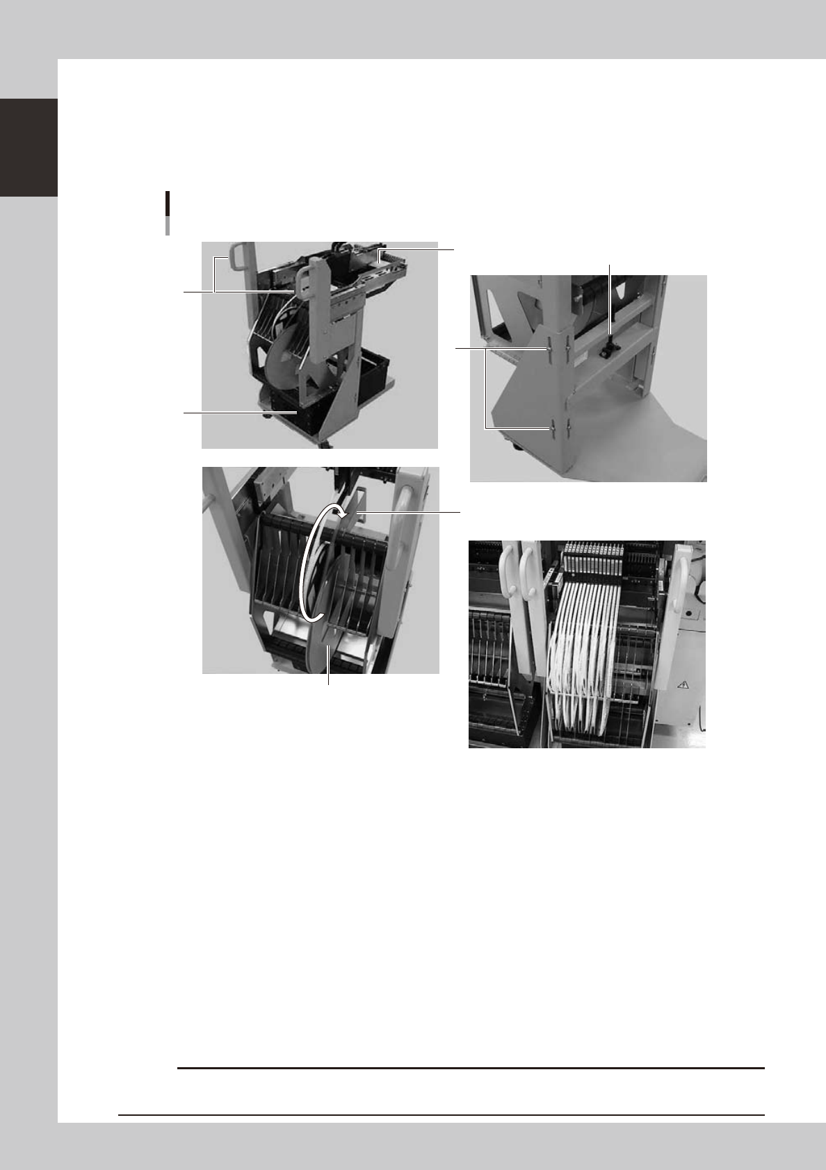
4.1.2 Feeder exchange carriage
The feeder exchange carriage allows feeder setup in advance for the next production boards. The feeders on
the feeder exchange carriage can be changed at one time.
n
Feeder exchange carriage
External view of feeder exchange carriage
1
2
4
6
5
3
Placing 7-inch reels continuously
A tape reel larger than 7 inches
23118-L7-00
1. Handle
Use this handle to move and position the feeder exchange carriage.
2. Feeder plate
Up to 24 SS feeders (8mm) can be installed on this feeder plate.
3. Vertical clamp bolts
If necessary to adjust the feeder plate height, loosen these bolts and change their clamping positions. (8 places)
4. Empty tape dump box (option)
This box is for catching empty tape after components have been picked up.
5. Height adjustment bolt
After loosening the vertical clamp bolts, turn this bolt to adjust the feeder plate height.
6. Reel holder
Each reel holder holds one tape reel (7 inches) for 8mm tape feeders.
When using a tape reel larger than 7 inches, raise this reel holder as shown above.
c
above.
1-15
1
Part names and functions
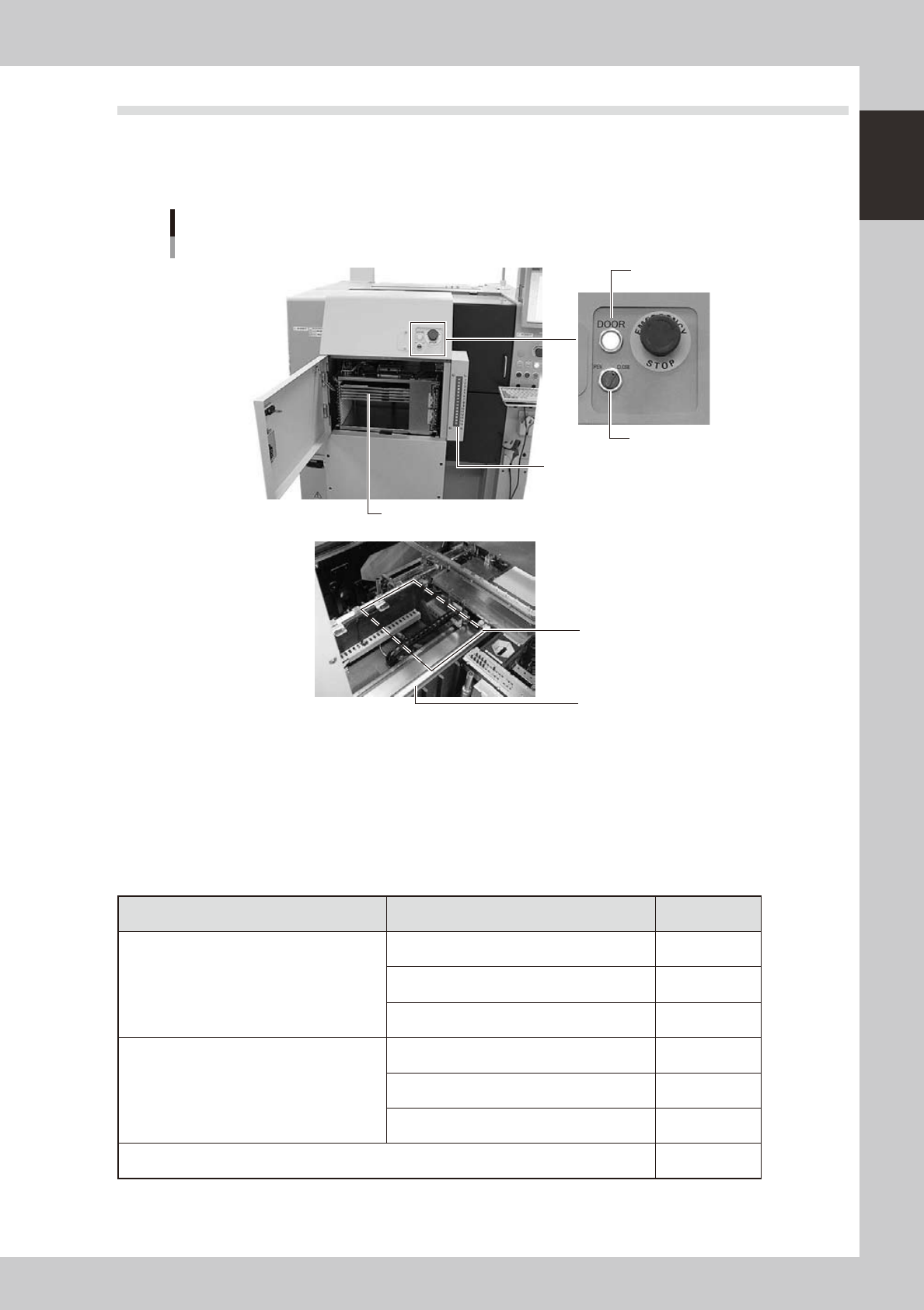
4.2 Supplying components from tray changer (ATS15)
Major part names and their functions of the tray changer (ATS15) are explained below.
4.2.1 ATS15 main unit
Tray changer main unit
ATS15
Pallet indicator
Guide rail
Pallet clamp position (work position)
Door switch
Door indicator
Pallet (Up to 15 pallets can be stored at 12.5mm pitch.)
23110-L7-00
Door switch
Setting this switch to "OPEN" unlocks the door and the DOOR indicator turns off.
Pallet indicator
The indicator lamps for the pallet No. set in the parts information are lit up. When the tray components on a pallet are
used up, the indicator lamp for that pallet No. flashes (see below). After setting new a pallet in the ATS15, press the
flashing indicator button to reset it.
n
Pallet indicator lighting pattern
Pallet condition Component condition Indicator status
One component type on one pallet
Components have been supplied. ON
Used up all components. Flashing
Components are currently being used. ON
Two or more components types on one pallet
All components on pallet have been supplied. ON
Used up all components. Flashing
Used up at least one type of component. Flashing
Components to be used are not specified in board data. OFF
1-16
1
Part names and functions
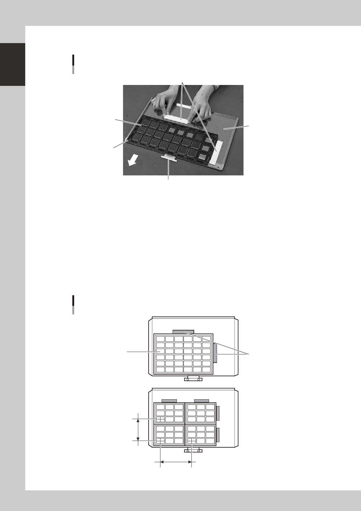
4.2.2 Pallet
Pallet
Setting tray components
Pallet pullout piece
Machine side
Tray mounting surface
Tray clamp magnets
Tray (components)
Pallet origin position
23121-L7-00
Pallet pullout piece
This piece is snagged by the ATS15 pallet pullout hook when pulling the pallet out from the magazine to the pallet stage
and when returning it to the magazine. This piece sets to the inner side when the pallet is inserted in the magazine.
Tray mounting surface
The pallet measures L350 × W220 and can hold component trays in sizes up to L325 × W195 (mm). The left front corner
in the above picture is the pallet origin position.
Tray clamp magnets
These are used to clamp the component tray to the tray mounting surface of the pallet.
n
Example of setting component trays
Several component trays can be set on one pallet (depending on the size of trays). Set the trays as described below.
Clamping the component tray
Using one tray
Using two or more trays
Tray pitch X
Clamping magnet
Tray
Tray pitch Y
23123-L7-00