EPL6127110_YS12PF_Ope_E.pdf - 第54页
1-17 1 Part names and functions n Pallet storage examples T he A TS15 holds up to 15 pallets (at a pallet storage pitc h of 12.5 mm). When tall components are to be used, change "P allet Pitch Z" in the parts i…
1-16
1
Part names and functions
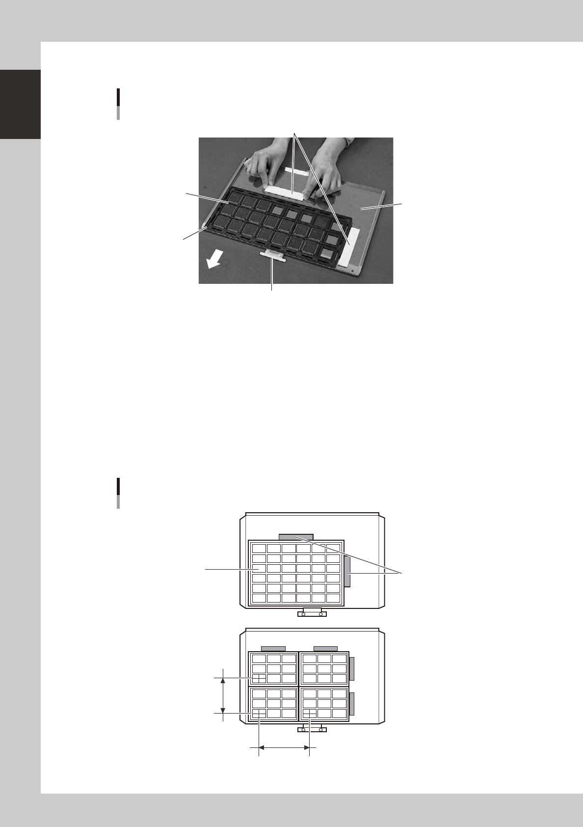
4.2.2 Pallet
Pallet
Setting tray components
Pallet pullout piece
Machine side
Tray mounting surface
Tray clamp magnets
Tray (components)
Pallet origin position
23121-L7-00
Pallet pullout piece
This piece is snagged by the ATS15 pallet pullout hook when pulling the pallet out from the magazine to the pallet stage
and when returning it to the magazine. This piece sets to the inner side when the pallet is inserted in the magazine.
Tray mounting surface
The pallet measures L350 × W220 and can hold component trays in sizes up to L325 × W195 (mm). The left front corner
in the above picture is the pallet origin position.
Tray clamp magnets
These are used to clamp the component tray to the tray mounting surface of the pallet.
n
Example of setting component trays
Several component trays can be set on one pallet (depending on the size of trays). Set the trays as described below.
Clamping the component tray
Using one tray
Using two or more trays
Tray pitch X
Clamping magnet
Tray
Tray pitch Y
23123-L7-00

1-17
1
Part names and functions
n
Pallet storage examples
The ATS15 holds up to 15 pallets (at a pallet storage pitch of 12.5 mm).
When tall components are to be used, change "Pallet Pitch Z" in the parts information to "×2", "×3" or "×4" depending on
the thickness of the "component + component tray" loaded in the pallet.
Pallet storage examples
12.5mm pitch
(Pallet Pitch Z: Normal)
37.5mm pitch
(Pallet Pitch Z: ×3)
25mm pitch
(Pallet Pitch Z: ×2)
Number of pallets stored in
magazine: 7
Number of pallets stored in
magazine: 15
Number of pallets stored in
magazine: 5
2
4
6
8
10
12
14
3
6
9
12
15
50mm pitch
(Pallet Pitch: ×4)
Number of pallets stored in
magazine: 3
3
7
11
15
23124-L7-10
n
For details on how to use the tray changer
Please refer to the following manuals for details on how to use the tray changer.
How to operate and handle : YS series option manual "ATS15"
How to create tray data : YS series programming manual
1-18
1
Part names and functions
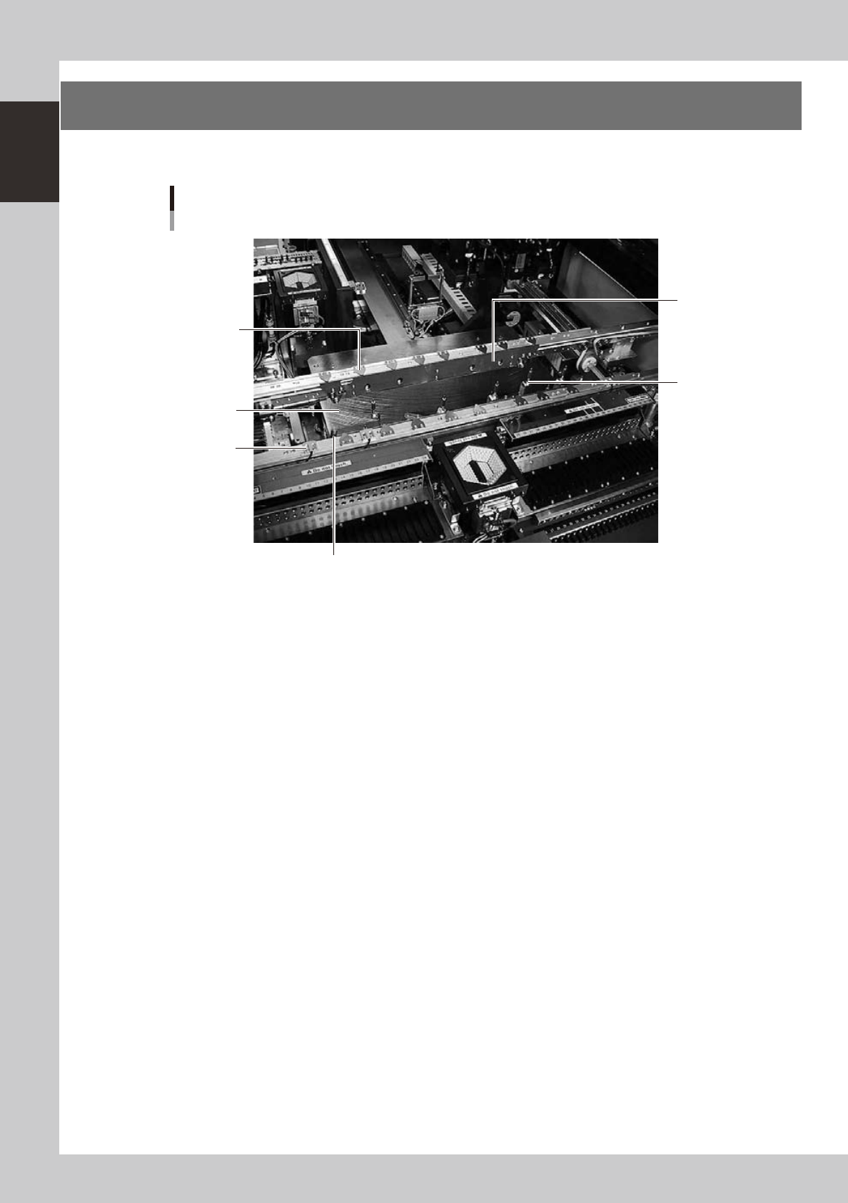
5.
Conveyor unit and component recognition system
The conveyor unit used to clamp a board in mounting position is described below.
4
5
2
1
6
Conveyor unit
3
23119-L7-00
1. Main stopper
When a board is carried in on the conveyor, the main stopper halts travel of the board in the component mounting
position.
2. Push-up plate
The push-up plate clamps the board up against the conveyor rails, with the supporter pins attached by magnet on the
push-up plate.
3. Push-up pins
These pins are arranged on the push-up plate and secure the board by pushing it up from the bottom.
4. Board hold plate (movable)
These plates hold the edges of the board from above when the board is clamped in the mounting position.
5. Board edge clamp unit
This unit clamps the board by pushing its edges up against the board hold plates.
6. Board sensor
Board sensors are arranged at the conveyor entrance and exit, "standby position", "board clamp position", etc.