EPL6127110_YS12PF_Ope_E.pdf - 第65页
Chapter 2 Basic operation Contents 1 1.1 Canceling emergency stop 2- 1 1.2 Clearing an error 2- 2 1.3 Typical err ors and troubleshooting 2- 3 8 …

1-27
1
Part names and functions
8.2 Tape cutting during board conveying
All tape cutters can operate with no special restrictions while a board is being conveyed to the exit after
component mounting is completed.
However, if there has been no tape feed whatsoever in tape feeders installed on the rear feeder plate since the
last tape cutting, then the rear tape cutters will not operate.
• Tape cut timing
Tape cutting operates at the timing that the boards are unclamped and conveyed to the exit after component mounting is
completed.
• Tape cutting conditions
Tape cutting is performed each time a board is conveyed to the exit after completing component mounting, and tape
cutting starts on all tape cutters that are set enabled.
8.3 Restrictions (caution)
Conditions affecting component mounting time
• If the tape feed lengths on the front and rear tape cutters simultaneously exceed the maximum cut length, then the
machine might delay component mounting to allow each tape cutter to cut the tape alternately.
• If the tape cutting speed drops due to a breakdown such as in the tape cutter valves or cylinder, then the machine
might delay component mounting.
Cautions for tape cutting during board conveying
Use caution when using board data where there is a large component feed length per feeder for each board, since the
tape that was cut off might hang up on the tape eject slot and does not reach the trash box.
Setting the standard cut length and maximum cut length
Hangs ups tend to occur during tape cutting performed during component mounting if the standard cut length and
maximum cut length were set to a large figure. Set these to a shorter figure if the tape does not easily eject after tape
cutting.
As a general guide, set the the standard cut length to 80mm, and the maximum cut length to 120mm.
n
NOTE
Operation buttons will be disabled during emergency stop or if an interlock is triggered.

Chapter 2 Basic operation
Contents
1
1.1 Canceling emergency stop 2-1
1.2 Clearing an error 2-2
1.3 Typical errors and troubleshooting 2-3
8
8
2.2 Setup screen 2-11
2.3 Unit screen 2-12
3. Starting and stopping the machine 2-17
3.1 Pre-operation check 2-18
3.2 Starting the machine 2-19
3.3 Warming up the machine 2-21
3
3.4.1 Conveyor unit setup flow 2-24
4. Preparing the component supply unit 2-26
4.1 Tape feeder 2-26
4.1.1 Setting the tape 2-26
4.1.2 Setting a tape feed pitch 2-31
4.1.3 Installation on a mounter 2-35
4.2 Wide multi-stick feeder 2-36
4.2.1 Installation of tracks and sticks 2-36
4.2.2 Installation on a mounter 2-39
4.3 Setting the tray components 2-40
4.3.1 Setting the component trays in the pallet 2-40
4.3.2 Setting a pallet in the ATS15 2-41
5. Settings on the mounter side 2-42
5.1 Setting the "Package" parameter. 2-42
7
2-1
2
asic operation
1. Before operation
The following explains how to cancel emergency stop and clear errors. Read before operating the machine.
n
Cautions during machine operation
• Do not turn off the compressed air during operation. The machine may malfunction, as pneumatic devices are not
correctly controlled.
• Before beginning maintenance work, always make sure that no air pressure remains in air cylinders.
n
Cautions during power outages
If a power outage (blackout) occurs during automatic machine operation, always turn the main power switch off to
prevent faulty operation or machine damage after power has been restored. Also remove the boards that remain in the
machine.
1.1 Canceling emergency stop
Follow these steps to cancel emergency stop.
1
Release the emergency stop button.
When the emergency stop button is pressed, turn it clockwise to release it.
2
Check safety.
Before continuing the procedure, check the surrounding area for safety.
3
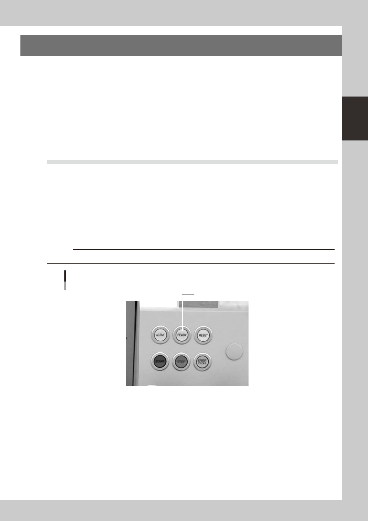
Press the [READY] button.
Pressing the [READY] button on the operation panel turns on the servomotors.
c
[READY] button
Press the [READY] button to turn on the servo.
23200-L6-00
4
Check the signal light and screen display.
Check that the red lamp of the signal light is off and the emergency stop sign on the top left (status
area) of the operation screen is now off.