EPL6127110_YS12PF_Ope_E.pdf - 第76页
2-11 2 asic operation 2.2 Setup screen T his section describes the operation buttons display ed on the Setup screen. Setup screen 1 2 3 4 5 6 7 8 9 11 10 12 14 15 16 18 17 13 24203-L6-10 Button name Function 1 History …
2-10
2
asic operation
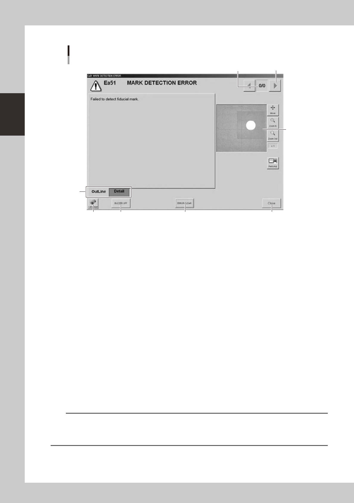
About error screen
Error screen
Mark detection error
1
2
3
7
46 5
[Error Switching] button
24202-L6-00
1. Error count display
Shows the currently displayed error and the total number of errors. If two or more errors occurred, use the [Error
Switching] buttons (right/left arrow buttons) to switch to other error screens.
2. Message switching tab
Outline:
Displays a message for the operator.
Detail:
Displays a message for the administrator/supervisor or service personnel. This tab does not appear unless a message is
available.
3. Recognition image display (component pickup error and mark recognition error screens)
If an error has occurred in image processing during component pickup or mark recognition, the error image is displayed
here.
4. [BUZZER OFF]
Turns off the buzzer.
5. [ERROR CLEAR]
Clears the error that has occurred.
6. [Language] button
Switches the language of the message displayed on the error screen.
7. [Close] button
Closes the error screen without clearing the error.
TIP
After closing the error screen by pressing the [Close] button, you can check the locations where errors have occurred
by opening the [Monitor] - [Production] tab. Pressing the [Error Detail] button on the [Production] tab screen redisplays
the error message. For more details on the [Production] tab screen, refer to Chapter 3, "Starting and ending
production".
2-11
2
asic operation
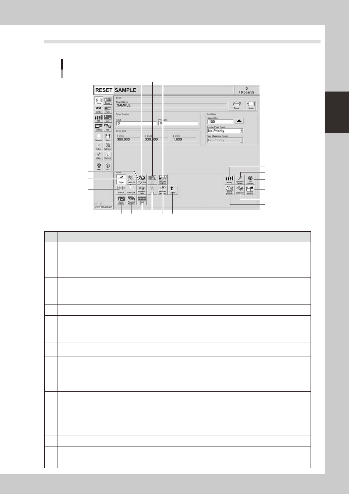
2.2 Setup screen
This section describes the operation buttons displayed on the Setup screen.
Setup screen
1
2
3
4
5
6
7 8 9
11
1012141516
18
17
13
24203-L6-10
Button name Function
1 History
Saves production history data, and saves or clear any desired items of "MIS" and "Unit log"
records. Also use this button when removing a storage medium from the machine.
2 Software Setting Sets machine screen display items, adds or deletes operators, and sets passwords.
3 Version Shows version information on application software and system.
4 System Backup
Makes a backup of machine coordinates, accuracy information, option device information and
standard coordinates necessary for machine operation or restores the data using the backup.
5 Database
Makes a backup of parts and mark database necessary for board production or restores the data
using the backup. Also sets the database locations.
6 Board Explorer Moves, backs up, restores or copies board data.
7 Cycle Stop
Stops machine operation just after mounting components on the current board, for example, to
check the mounted results or to prevent the board from flowing to the downstream machine.
8 Convey-out Stop
Stops machine operation after mounting components on all boards on the conveyor and
transferring them to the downstream machine.
9 Halfway Continue
After stopping the machine for some reason during component mounting and resetting the data,
pressing this button loads that data to resume component mounting from the next mount point.
10 Width Changes the conveyor width.
11 Measure Nozzles Not currently used.
12 Step
Temporarily stops the machine at a specific position, for example, during initial component
mounting, test mounting, or trouble analysis.
13 Required Parts
Displays the component types and feeder positions that are set up for the production to be
started.
14 Block Skip
This button becomes active when board data with block distribution performed is loaded.
Pressing this button displays the "Block Skip Utility" dialog box that allows you to set whether to
skip mounting components in each block.
15 Required Nozzles Displays a list of nozzles to be used.
16 Check Nozzles Not currently used.
17 Tray Cnt Displays the number of tray components that have been used.
18 Feed Bulk Not currently used.
2-12
2
asic operation
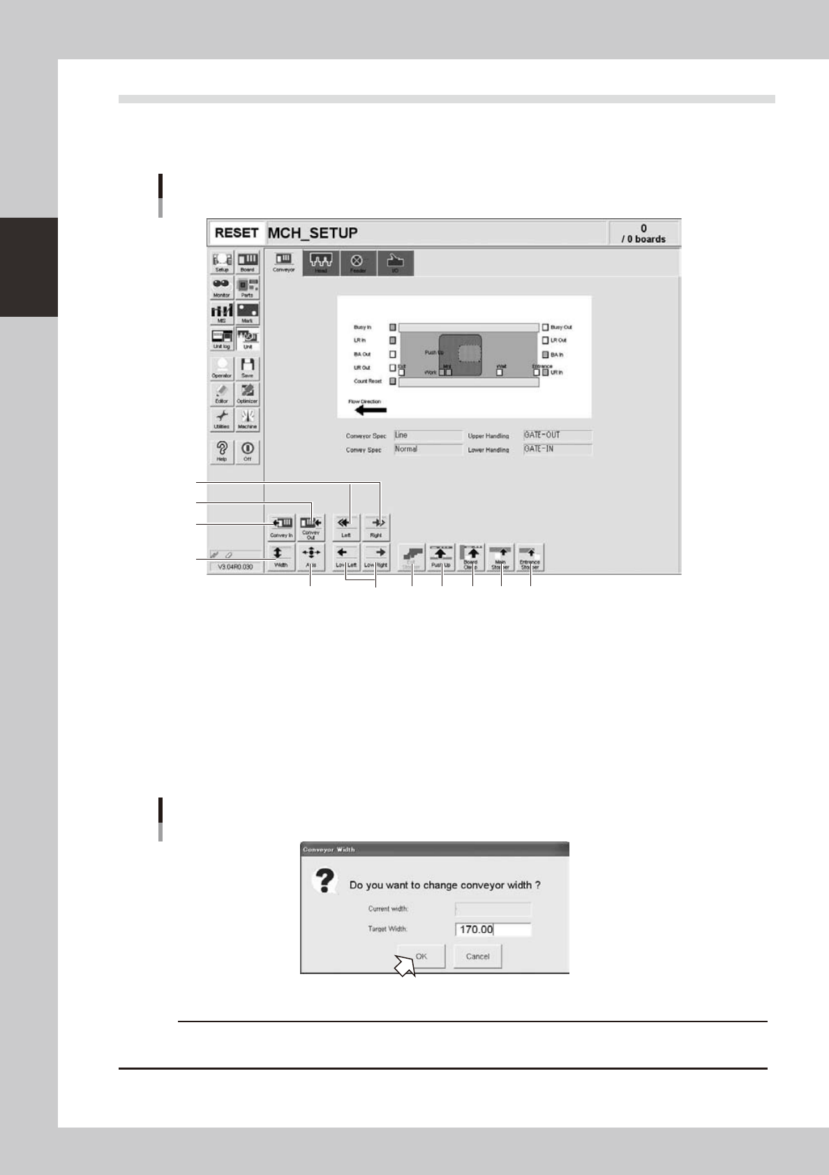
2.3 Unit screen
This section describes the manual operation buttons on the Unit screen.
n
Manual conveyor operation
1
Conveyor manual buttons
3
2
4
5
6
7 8 9 10 11
24204-L6-00
1. Convey In
Moves the board from the conveyor entrance or standby position to the clamp position and clamps it.
2. Convey Out
Unclamps the board and moves it to the exit stopper position.
3. [Width] button
Use this button to adjust the conveyor width to match the width of boards to be produced.
Pressing this button displays the "Conveyor Width" dialog box. Check the conveyor width and press the [OK] button. The
conveyor rail automatically changes to the specified width.
"Conveyor Width" dialog box
24205-L6-00
c
conveyor units.