Utah-94-721002-System-Manual.pdf - 第116页
mä~ëã~ä~Ä póëíÉãNMM lñÑçêÇ =fåëíêìã Éåíë= mä~ëã~ =qÉÅÜåçäçÖó == System Manual The page provides the following facilities: Show Pumps button Displays the Pump Control page Message field Displays status messages about the …
System Manual lñÑçêÇ=fåëíêìãÉåíë=mä~ëã~=qÉÅÜåçäçÖó== mä~ëã~ä~ÄpóëíÉãNMM
f) Process chamber rotary vane/dry pump.
g) Automatic load lock transfer arm (click red dot to insert/withdraw arm).
h) Automatic load lock isolating valve.
i) Automatic load lock vent valve.
j) Automatic load lock dry/rotary vane pump.
k) Slit valve.
RKUKUKN= qê~åëÑÉêêáåÖ=ï~ÑÉêë=áå=ëÉêîáÅÉ=ãçÇÉ=
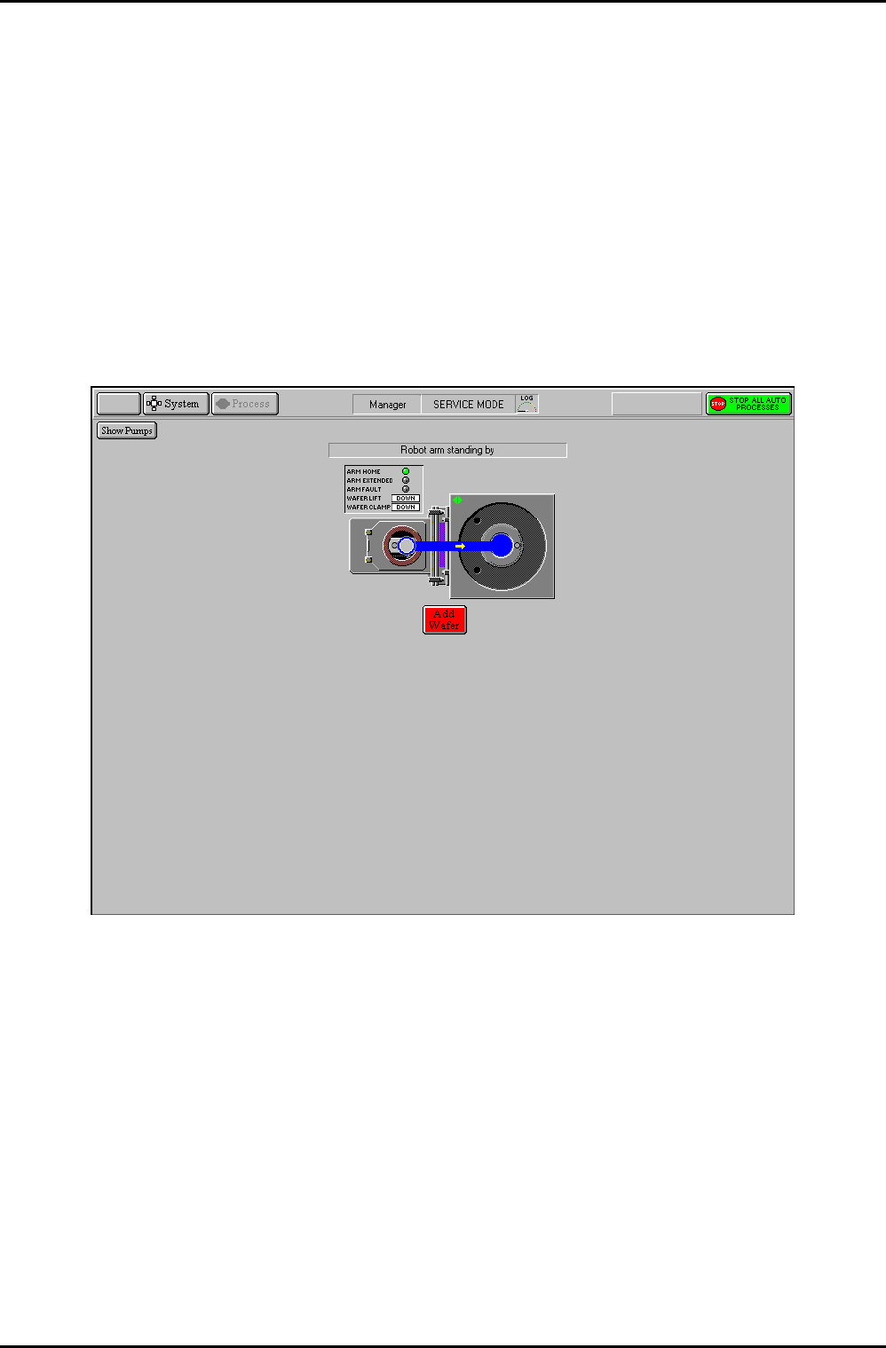
To transfer wafers between chambers in service mode, click on the wafer mimic (either in the
Automatic load lock or process chamber). The following screen is displayed:
Fig 5.20: Wafer transfer in service mode
Click on the wafer destination. The wafer will be transferred.
The ADD WAFER button is used to inform the system that a wafer is present. This facility
would be used if the machine were powered-up with a wafer in the Automatic load lock. The
legend on this button changes to KILL WAFER when a wafer is present, enabling the selected
wafer to be removed from system memory.
Operating Instructions
Printed: 22-Mar-06, 10:42 Page 5-49 of 52 UC Davis 94-721001 Issue 1: March 06
mä~ëã~ä~ÄpóëíÉãNMM lñÑçêÇ=fåëíêìãÉåíë=mä~ëã~=qÉÅÜåçäçÖó== System Manual
The page provides the following facilities:
Show Pumps
button
Displays the Pump Control page
Message field
Displays status messages about the wafer transfer.
Add/Kill Wafer
button
The ADD WAFER button is used to inform the system that a wafer is
present. This facility would be used if the machine were powered-up with
a wafer in the Automatic load lock. The legend on this button changes to
KILL WAFER when a wafer is present, enabling the selected wafer to be
removed from system memory.
Wafer transfer
path
Displayed when the wafer mimic has been clicked. An arrow indicates the
direction of the possible transfer. Clicking on the destination will cause
the transfer to be carried out.
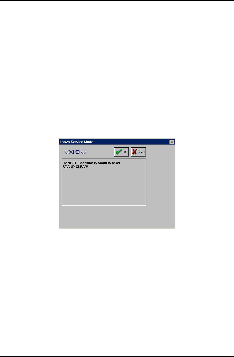
RKUKUKO= bñáíáåÖ=Ñêçã=ëÉêîáÅÉ=ãçÇÉ=
To exit from service mode, select the system menu and then the Exit Service option. The
following dialogue box is displayed:
Ensure that there are no personnel close to the system, and then select the OK button.
After exiting from service mode, the system configuration will depend on which service mode
facilities were used as follows:
a) If no service mode facilities were used, e.g. no valves were open or closed; the system
configuration will be the same as it was before entering service mode.
b) If the service facilities were used, the system configuration will depend on which of
the facilities were used as follows.
To prevent damage to the system, any chamber which had any of its features altered in
service mode, e.g. valves opened/closed, pumps turned on/off etc., will have its pumping
stopped. All other chambers will continue to be pumped.
To return the chamber which had its pumping stopped to the pumping or vent state, click on
the associated Stop button, and then on the Evacuate button or the Vent button as
required. The chamber will then pump down or vent.
Operating Instructions
UC Davis 94-721001 Issue 1: March 06 Page 5-50 of 52 Printed: 22-Mar-06, 10:42
System Manual lñÑçêÇ=fåëíêìãÉåíë=mä~ëã~=qÉÅÜåçäçÖó== mä~ëã~ä~ÄpóëíÉãNMM
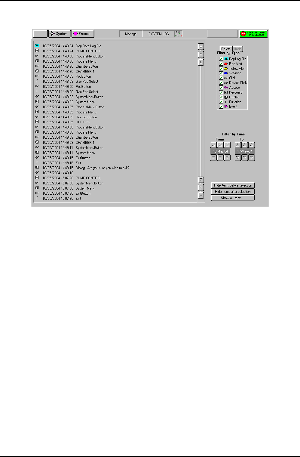
RKUKV= póëíÉã=äçÖ=é~ÖÉ=
Fig 5.21: System log page
The system log page allows logged system events to be viewed. A filter facility allows the
viewed events to be displayed by event type and time of occurrence.
The page provides the following features:
Event list: A scrollable list of events in date/time order. Each event is categorised
by an icon, and an event description is given. Use the scrollbar and
associated buttons to move the list up or down by a single event, a
page of events or to the end of the list.
Delete button
Removes the selected event(s) from the Event list.
Undo button
Only active after a Delete action. Restores the last deleted event.
Filter by
Event Type
panel:
A list of event types with associated checkboxes. Use this panel to select
the events to display in the Event list. A checkbox showing an ‘x’
indicates that the associated event type will not be displayed. A
checkbox showing a ‘9’ indicates that the associated event type will be
displayed.
Filter by time
controls:
Use these controls to select events occurring in a time range to be
displayed.
Hide events
before
selection
button
Displays all events after and including the highlighted event.
Operating Instructions
Printed: 22-Mar-06, 10:42 Page 5-51 of 52 UC Davis 94-721001 Issue 1: March 06