Utah-94-721002-System-Manual.pdf - 第141页
System Manual = lñÑçêÇ=fåëíêìãÉåíë=mä~ëã~=qÉÅÜåçäçÖó= mä~ëã~ä~Ä = póëíÉã=NMM TK= mêçÅÉëë=ÖìáÇÉ=C=Öäçëë~êó= Process Guide and Glossary Printed: 25 May 2005 10:16 Page 7-1 of 2 Issue 1: December 03
mä~ëã~ä~ÄpóëíÉãNMM lñÑçêÇ=fåëíêìãÉåíë=mä~ëã~=qÉÅÜåçäçÖó== System Manual
WARNING
BEFORE PROCEEDING WITH ANY MAINTENANCE WORK, READ SECTION 1 - HEALTH AND SAFETY.
SKNQ= ^ìíçã~íáÅ=äç~Ç=äçÅâ=ÉåÇ=ÉÑÑÉÅíçê=~ÇàìëíãÉåíë=Ñçê=ÇáÑÑÉêÉåí=
ï~ÑÉê=ëáòÉë=
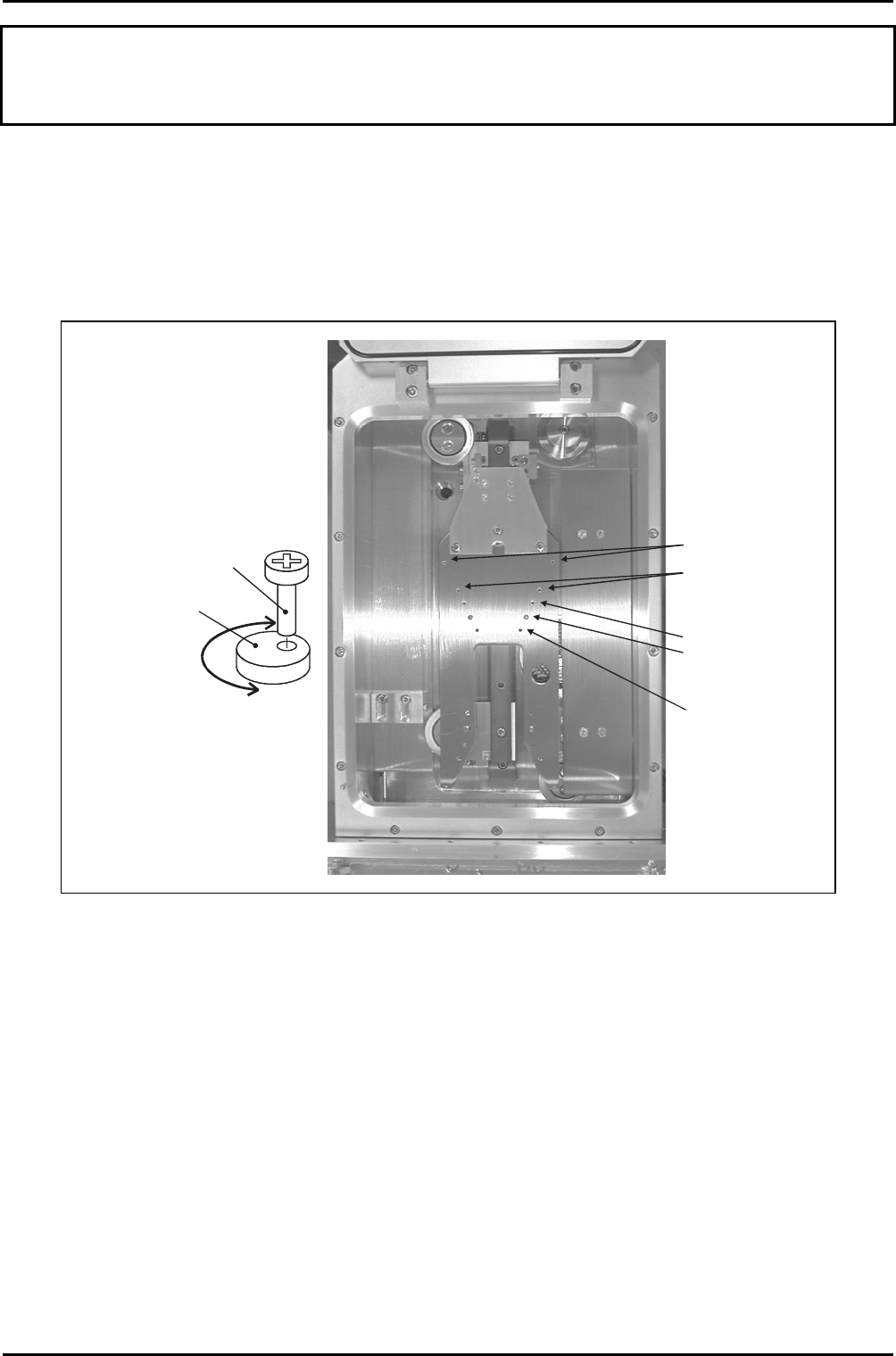
The automatic load lock end effector can accommodate wafer diameters of 3” to 8”. This is
achieved using a series of pairs of holes appropriately spaced for the different wafer sizes
into which concentric cams are secured. See Fig 6.3.
Concentric cam
locations for 8“
wafers
Concentric cam
locations for 6“
wafers
Concentric cam
locations for 4“
wafers (cams shown
in this position)
Location for 5“ wafers
Location for 3“ wafers
Concentric cam
detail
Securing
screw
Cam
Rotating the cam
about the securing
screw provides a
small forwards/
backwards adjustment
of the wafer position.
Fig 6.3: End effector wafer size adjustments
To set up the end effector for a wafer size different to that previously processed, use the
following procedure:
1) If necessary, vent the automatic load lock.
2) Open the automatic load lock’s lid.
3) Wearing powder-free gloves, remove both concentric cams/securing screws from the
end effector, then fit them into the appropriate holes for the wafer size to be
processed. See Fig 6.3.
4) Close the automatic load lock’s lid, then carry out a test wafer load into a process
chamber. Ensure that the wafer is located centrally on the lower electrode. If
necessary, rotate the concentric cams until the wafer is located centrally.
Maintenance
UC Davis 94-721001 Issue 1: March 06 Page 6-22 of 22 Printed: 22-Mar-06, 7:41

System Manual= lñÑçêÇ=fåëíêìãÉåíë=mä~ëã~=qÉÅÜåçäçÖó= mä~ëã~ä~Ä
=
póëíÉã=NMM
TK= mêçÅÉëë=ÖìáÇÉ=C=Öäçëë~êó=
Process Guide and Glossary
Printed: 25 May 2005 10:16 Page 7-1 of 2 Issue 1: December 03

mä~ëã~ä~Ä
=
póëíÉã=NMM= lñÑçêÇ=fåëíêìãÉåíë=mä~ëã~=qÉÅÜåçäçÖó= System Manual
TKN= ^Äçìí=íÜáë=pÉÅíáçå=
This Section contains the OIPT ‘Process Guide’ document. Note that this document includes a
Glossary of Terms.
Process Guide and Glossary
Issue 1: December 03 Page 7-2 of 2 Printed: 25 May 2005 10:16