Utah-94-721002-System-Manual.pdf - 第201页
Installation Data = lñÑçêÇ=fåëíêìãÉåíë=mä~ëã~=qÉÅÜåçäçÖó mä~ëã~ä~Ä póëíÉãNMM OK= fåëí~ää~íáçå=áåÑçêã~íáçå= OKN= aáãÉåëáçåë= System dimensions are given in Fig 1, Fig 2 a nd Fig 3. Gas handling component dimensions are gi…

mä~ëã~ä~ÄpóëíÉãNMM= lñÑçêÇ=fåëíêìãÉåíë=mä~ëã~=qÉÅÜåçäçÖó Installation Data
NK= fåíêçÇìÅíáçå=
This installation specification document gives information about the mä~ëã~ä~ÄpóëíÉãNMM
to
enable customers to prepare the required environment for the system.
Note that all dimensions shown in these data sheets are typical; precise dimensions depend
on the actual equipment fit. All dimensions are given in millimetres unless otherwise stated.
NOTE:
All information, services, dimensions etc., refer only to the
mä~ëã~ä~ÄpóëíÉãNMM, i.e. plasma processing at up to 200 mm wafers in
MESC compatible chambers.
Oxford Instruments Plasma Technology conducts a programme of continual product
development, and reserves the right to change the design and/or specification of equipment
without notice. The details contained in this document were correct at the time of printing
but should be confirmed immediately prior to delivery. Details of the clean room interface
will be advised at the time of delivery.
Installation Data (ICP 180)
Issue 5: June 05 Page 4 of 18 Printed: 22-Mar-06, 6:57

Installation Data= lñÑçêÇ=fåëíêìãÉåíë=mä~ëã~=qÉÅÜåçäçÖó mä~ëã~ä~ÄpóëíÉãNMM
OK= fåëí~ää~íáçå=áåÑçêã~íáçå=
OKN= aáãÉåëáçåë=
System dimensions are given in Fig 1, Fig 2 and Fig 3. Gas handling component dimensions are
given in Fig 6, Fig 7 and Fig 8. Pump dimensions are given in Section 6. Heater/chiller
dimensions are given in Section 7.
OKO= tÉáÖÜíë=
Typical weights of system components:
2-frame system: 320 kg
3-frame system: 390 kg
6-line Gas pod: 35 kg
12-line Gas pod: 65 kg
Pumps: See Section 6 (Pump set information).
Heater/chillers: See Section 7 (Heater/chiller information).
OKP= eÉ~í=äç~Ç=
The typical heat load for the clean room installation is:
Operating: 2 kW
Passive: 1.5 kW
Note that these specifications do not include externally sited components, e.g. pumps,
heater/chillers, transformers, etc..
Installation Data (ICP 180)
Printed: 22-Mar-06, 6:57 Page 5 of 18 Issue 5: June 05
mä~ëã~ä~ÄpóëíÉãNMM= lñÑçêÇ=fåëíêìãÉåíë=mä~ëã~=qÉÅÜåçäçÖó Installation Data
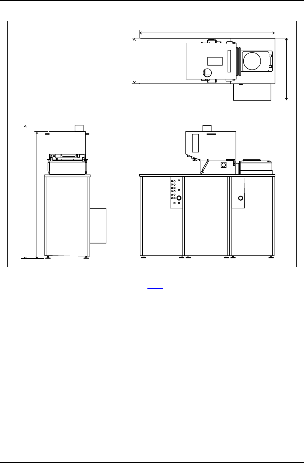
1630
747
550
1516
1592
SERVICE ACCESS
OIPT RECOMMENDS THAT AT LEAST 600mm
SERVICE ACCESS SPACE IS ALLOWED BETWEEN
ANY OBSTACLE (E.G. WALLS, PARTITIONS, ETC.)
AND SERVICEABLE ITEMS, E.G. THE POWER
DISTRIBUTION UNIT.
Fig 1: ICP 180 system layout (3-frame)
NOTE: For services panel details, see Fig 4.
Installation Data (ICP 180)
Issue 5: June 05 Page 6 of 18 Printed: 22-Mar-06, 6:57