Utah-94-721002-System-Manual.pdf - 第225页
System Manual lñÑçêÇ= fåëíêìãÉ åíë=m ä~ëã~ = qÉÅÜåçäçÖó== lfmq=póëíÉãë Pressure: Adjustable 0.7 to 4.2 bar (10 to 60 psi). Chiller / heat exchanger to be fitted with a bypass having a ca pacity of 100% of rated flow. Tem…
lfmq=póëíÉãë lñÑçêÇ=fåëíêìãÉåíë=mä~ëã~=qÉÅÜåçäçÖó== System Manual
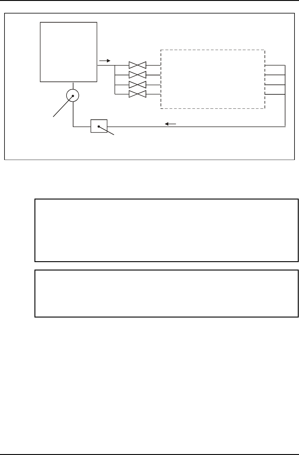
DEDICATED
HEAT EXCHANGER
OR
CHILLER
PLASMALAB
OR
IONFAB
SYSTEM
ISOLATION
VALVES
10-MICRON METAL MESH FILTER
MAXIMUM PRESSURE DROP AT
RATED FLOW RATE 0.15 BAR (2.2 PSI)
TOTAL WATER FLOW
METER OF APPROPRIATE
RANGE
(FITTED WITH AN
EXTERNAL BYPASS
HAVING A CAPACITY OF
100% FLOW)
Fig 2.1: Recommended basic recirculation installation
OKNKN= j~åÇ~íçêó=péÉÅáÑáÅ~íáçåë=Ñçê=êÉÅáêÅìä~íÉÇ=ï~íÉê=ëóëíÉãë=
CAUTION
If clear (i.e. transparent) tubing is exposed to sunlight, algal growth can develop,
which can restrict coolant flow.
It is MANDATORY that clear tubing is not used in any part of the cooling system.
OIPT recommends the use of either black or dark green tubing.
CAUTION
It is the customer's responsibility not to exceed a pressure of 4.2 bar, or other
limit that has been set for the system. Exceeding this safe pressure may cause
irreparable damage to system components.
The water must be kept warm enough to prevent condensation on chamber surfaces and
outside system components. This applies to those parts of the system inside the clean room
and those parts in a service area. Condensation can damage components such as RF power
supplies, ferrofluidic seals and automatch units. Any damage so caused cannot be covered by
the system warranty.
Services Specifications
Issue 16: April 05 Page 6 of 22 Printed: 6-Jan-06, 8:44
System Manual lñÑçêÇ=fåëíêìãÉåíë=mä~ëã~=qÉÅÜåçäçÖó== lfmq=póëíÉãë
Pressure: Adjustable 0.7 to 4.2 bar (10 to 60 psi). Chiller / heat exchanger
to be fitted with a bypass having a capacity of 100% of rated
flow.
Temperature range: See system installation data sheets.
Minimum flows: See system installation data sheets.
Cooling capacity: See system installation data sheets.
Coolant: Hexid A40 (OIPT Part No. G/WATER/SUN/007 for 15 litres)
2
. This
product is propylene glycol based, and is pre-diluted ready for
use. See sub-section 2.1 for the warranty impact of not using
this product.
Filtration: 10 micron metal mesh water filter. Maximum pressure drop
0.15 bar (2.2 psi) at rated flow. For example, filter element
Balston SMC-100-12-10.
OKO= qçí~ä=içëë=`ççäáåÖ=
Municipal (drinking) water may be used in total loss cooling of the system in situations
where clean water is freely available, but only if the water meets the specification in sub-
section 2.2.1. In case of any doubt, obtain the water specification from the water utility
company, and consult with OIPT. It is not practical to use total loss cooling where the water
temperature is critical.
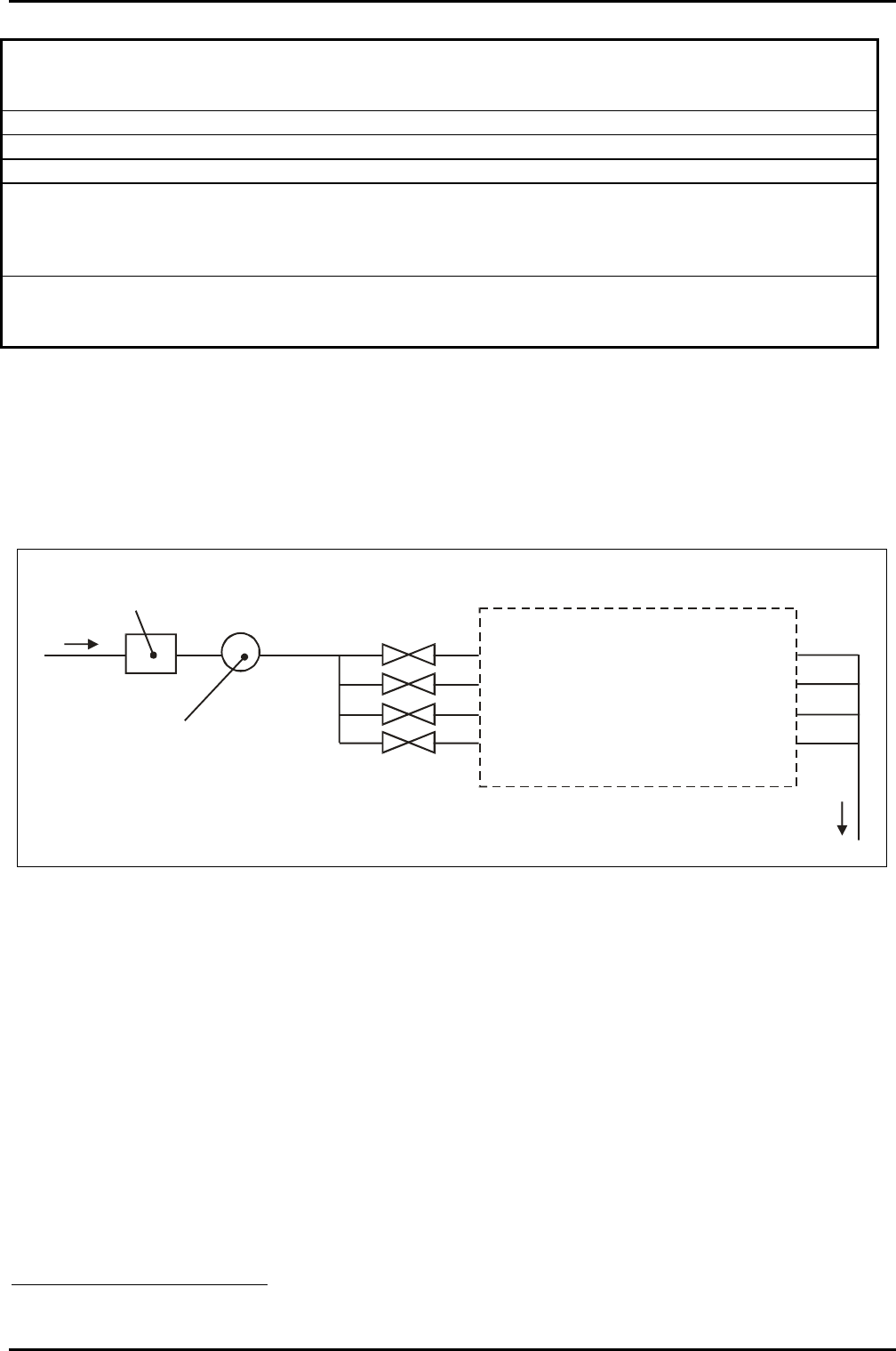
PLASMALAB
OR
IONFAB
SYSTEM
ISOLATION
VALVES
FILTER
0.9 MICRON FULL FLOW
TOTAL WATER FLOW
METER OF APPROPRIATE
RANGE
DRAIN
Fig 2.2: Recommended basic total loss installation
2
To order replacement fluid, check the capacity of the model of heater/chiller to be fitted to the system. Also allow at least 5 litres
for the system and connecting lines, or more if necessary.
Services Specifications
Printed: 6-Jan-06, 8:44 Page 7 of 22 Issue 16: April 05
lfmq=póëíÉãë lñÑçêÇ=fåëíêìãÉåíë=mä~ëã~=qÉÅÜåçäçÖó== System Manual
OKOKN= j~åÇ~íçêó=péÉÅáÑáÅ~íáçåë=Ñçê=íçí~ä=äçëë=ÅççäáåÖ=ëóëíÉãë=
CAUTION
If clear (i.e. transparent) tubing is exposed to sunlight, algal growth can develop,
which can restrict coolant flow.
It is MANDATORY that clear tubing is not used in any part of the cooling system.
OIPT recommends the use of either black or dark green tubing.
CAUTION
It is the customer's responsibility not to exceed a pressure of 5 bar, or other limit
that has been set for the system. Exceeding this safe pressure may cause
irreparable damage to system components.
If total loss cooling with municipal water (drinking quality water) is used in the system or in
the pumps, the water quality must meet the following specifications. Note that increased
maintenance will be required if this water is used directly in the system as well as in the
pumps.
The water must be kept warm enough to prevent condensation on chamber surfaces and
outside system components. This applies to those parts of the system inside the clean room
and those parts in a service area. Condensation can damage components such as RF power
supplies, ferrofluidic seals and automatch units. Any damage so caused cannot be covered by
the system warranty.
• Pressure: 4 to 5 bar. Backpressure from the drain must be less than 1
bar.
• Temperature: 10ºC to 25ºC
• pH: 7 to 8
• Oxygen: Greater than 4mg/litre
• CO
2
and NH
3
: Less than 10mg/litre
• Chloride: Less than 100mg/litre
• Calcium
Carbonate:
Less than 75mg/litre
• Filtration: To 0.9 micron full flow, for example filter element Balston
200-50-50 or 200-95-50.
Services Specifications
Issue 16: April 05 Page 8 of 22 Printed: 6-Jan-06, 8:44