Utah-94-721002-System-Manual.pdf - 第228页
lfmq=póëíÉãë lñÑç êÇ=fåë íêìãÉåí ë=m ä~ë ã~=qÉÅÜåçäçÖó== System Manual “ WARNING. High leakage current. Earth connection essential before connecting su pply. " PKNKO= kÉìíê~ä=ëìééäó=ÄçåÇáåÖ= WARNING THE NEUTRAL COND…
System Manual lñÑçêÇ=fåëíêìãÉåíë=mä~ëã~=qÉÅÜåçäçÖó== lfmq=póëíÉãë
PK= bäÉÅíêáÅ~ä=ëìééäó=
Classification: For European Community customers who need this information: The systems
are classified as Class A, Group 2 as defined in EN 55011 Clause 4.
Phase 1
conductor
Phase 2
conductor
Phase 3
conductor
Neutral
conductor
SAFETY
ISOLATION
BOX
3-Phase
supply
to
system
PLASMALAB
OR
IONFAB
SYSTEM
INDEPENDENT
EARTH (GROUND)
3-phase supply
or transformer
secondary
winding
Hand
Operated
NEUTRAL CONDUCTOR
BONDED TO EARTH
(GROUND)
Combined Circuit Breaker
to protect transformer
to system phase conductors
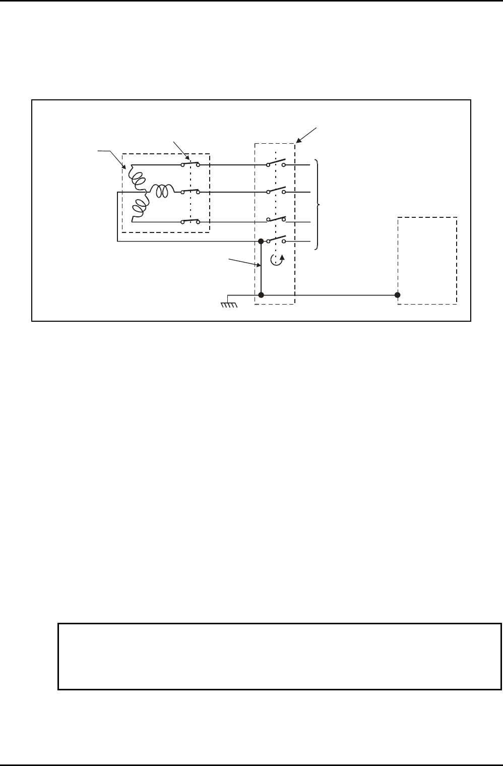
Fig 3.1: Recommended electrical installation
NOTES:
a) The combined Circuit Breaker MUST break all phases if any one phase
exceeds the set current limit.
b) The trip rating of the Circuit Breaker depends on the system type and the
supply voltage to the system.
c) The current-carrying capacity of the cables between the Circuit Breakers
and the system must be greater than the trip rating of the Circuit Breaker.
For example, if a 32A Circuit Breaker is fitted then a cable having
conductors of a minimum rating of 40A (32A x 125%) is required. The
conductors will have a minimum Cross Sectional Area (CSA) of 6.0 mm
2
.
PKN= póëíÉã=É~êíÜáåÖ=~åÇ=ÄçåÇáåÖ=
PKNKN= b~êíÜ=ÅçååÉÅíáçå=
To meet international standards for RF interference, our systems are fitted with filtration on
the mains supply inputs. As a result, there is significant leakage to earth (ground) from the
mains supply.
WARNING
IT IS ESSENTIAL THAT AN EARTH CONNECTION IS MADE BEFORE CONNECTING THE
SUPPLY.
International standard IEC950, section 5.2, requires that a label is attached at the point where
the system is connected to the factory electricity supply: either to the safety isolation box, or
to the transformer, or to the electrical supply outlet socket. This label must contain the
following text:
Services Specifications
Printed: 6-Jan-06, 8:44 Page 9 of 22 Issue 16: April 05
lfmq=póëíÉãë lñÑçêÇ=fåëíêìãÉåíë=mä~ëã~=qÉÅÜåçäçÖó== System Manual
“WARNING.
High leakage current.
Earth connection essential before connecting supply."
PKNKO= kÉìíê~ä=ëìééäó=ÄçåÇáåÖ=
WARNING
THE NEUTRAL CONDUCTOR MUST BE BONDED TO THE EARTH (GROUND)
CONDUCTOR. IF THIS IS NOT DONE ALREADY IN THE FACTORY SUPPLY, THEN IT
MUST BE DONE AT THE SAFETY ISOLATION BOX AS SHOWN IN Fig 3.1. IF AN
ISOLATING TRANSFORMER IS FITTED, THEN THE NEUTRAL CONDUCTOR OF THE
TRANSFORMER SECONDARY MUST BE BONDED TO THE EARTH (GROUND)
CONDUCTOR.
PKNKP= oÉëáÇì~ä=`ìêêÉåí=`áêÅìáí=_êÉ~âÉêë=
Customers sometimes wish to fit a Residual Current Circuit Breaker (RCCB), also known as an
Earth Leakage Circuit Breaker (ELCB, or ELB) to the electrical supply to the system. This is not
recommended for this type of equipment, and a 30mA breaker is likely to trip often, due to
the leakage caused by the filters on the power lines. This leakage is in accordance with
International standard IEC950 section 5.2.
a) If you must fit an ELB, we strongly recommend a minimum current of 100mA.
b) Even a 100mA circuit breaker may trip, and we accept no responsibility if this turns
out to be the case.
PKO= j~åÇ~íçêó=péÉÅáÑáÅ~íáçåë=Ñçê=ÉäÉÅíêáÅ~ä=áåëí~ää~íáçåë=
• Connection: In accordance with local regulations via a safety isolation
box, lockable in the OFF position, mounted adjacent to the
machine.
• Configuration: 3-phase, star ("Y") with a grounded neutral supply
connected to the centre point. An independent earth
(ground) is required.
• Maximum
Current:
The Maximum Current required by the system is given in the
relevant system installation data sheets.
• Voltage &
Frequency:
380V -10% to 415V +6% or 208V +/-10% phase-to-phase.
Frequency to be 50Hz or 60Hz. Note that voltage and
frequency cannot be changed from the values specified at
the time of ordering.
• Safety
Earthing:
The system safety earthing must be in accordance with local
Electrical Regulations. See Fig 3.1.
Services Specifications
Issue 16: April 05 Page 10 of 22 Printed: 6-Jan-06, 8:44
System Manual lñÑçêÇ=fåëíêìãÉåíë=mä~ëã~=qÉÅÜåçäçÖó== lfmq=póëíÉãë
QK= `çãéêÉëëÉÇ=~áê=
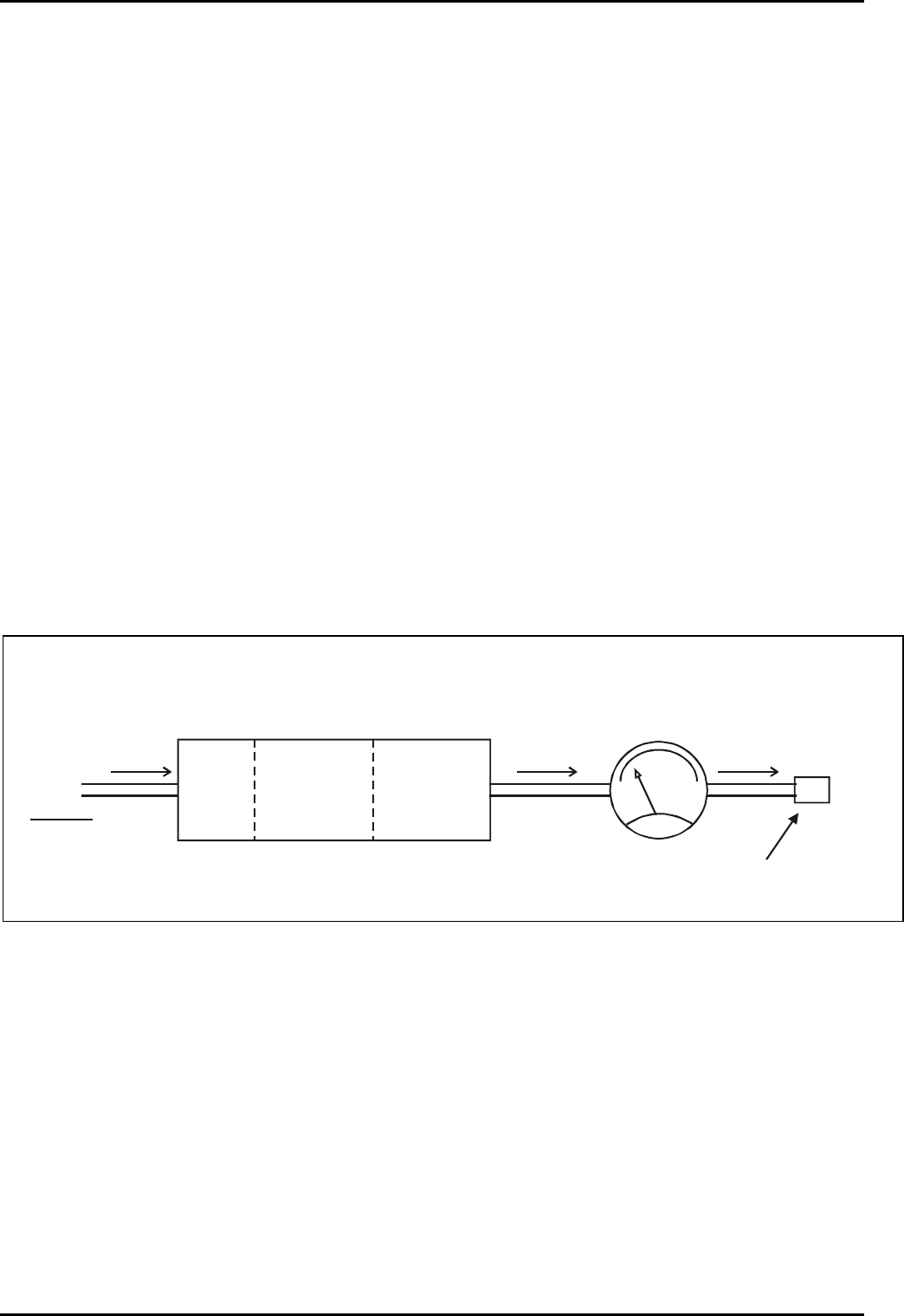
A dry and clean compressed air supply at a minimum pressure of 6 bar (90 psig) must be fed
to a customer-supplied air filter/mist separator/pressure regulator unit mounted adjacent to
the machine. A suitable unit is supplied by SMC (part No. AC 2030); other units to the same
specification can be used. Maximum safe pressure in the customer's feed to the regulator
is determined by the regulator used (9.9 bar (148.5 psig) for the SMC unit).
The supply to the system must be monitored by a pressure gauge having a range of 0 to 10
bar (0 to 150 psi). The pressure regulator must be fitted with a stop to prevent a pressure
greater than 6 bar from being supplied to the system. The pressure to be used will be set
during commissioning of the system.
The following air filter/mist separator/pressure regulator unit components are recommended:
Air filter: SMC AF2000-02D with filter element 1129116A.
Mist separator:
SMC AFD2000-02D with filter element 63092. This filter element
must be changed annually. Note that as this item is not
supplied by OIPT, its maintenance is not included in the system
manuals.
Regulator with gauge: SMC AR2001-02G.
Spacers: 2 off SMC Y20L.
FILTER
MIST
SEPARATOR
ADJUSTABLE
PRESSURE
REGULATOR
DRY AND CLEAN
AIR SUPPLY
MINIMUM PRESSURE
6 BAR (90 PSIG)
PRESSURE
GAUGE
0 TO 10 BAR
(0 TO 150 PSIG)
SMC COMPONENTS
OR EQUIVALENT
COMPRESSED
AIR SUPPLY TO
PLASMALAB OR
IONFAB SYSTEM
(SEE SPECIFICATION)
6 MM
PUSH-FIT
CONNECTOR
Fig 4.1: Recommended compressed air supply installation
Services Specifications
Printed: 6-Jan-06, 8:44 Page 11 of 22 Issue 16: April 05