Utah-94-721002-System-Manual.pdf - 第233页
System Manual lñÑçêÇ= fåëíêìãÉ åíë=m ä~ëã~ = qÉÅÜåçäçÖó== lfmq=póëíÉãë SKNKO= fåëí~ää~íáçå=çÑ=äçï=î~éçì ê=éêÉëëìêÉ=Ö~ëÉë=EÉKÖK=pá`ä Q I=_`ä P I=` Q c U F= The low vapour pressure can lead to condensation in the gas suppl…
lfmq=póëíÉãë lñÑçêÇ=fåëíêìãÉåíë=mä~ëã~=qÉÅÜåçäçÖó== System Manual
SK= mêçÅÉëë=Ö~ëÉë=
REGULATOR 0.5 BAR TO 5 BAR
(7 TO 75 PSIG) LOCATED
ADJACENT TO THE SYSTEM
SUPPLY TO
GAS POD
OR INTERNAL
GAS LINE
MINIMUM PRESSURE
3 BAR (45 PSIG)
ALL FITTINGS,
REGULATOR AND
FILTER TO BE
SEMICONDUCTOR
GRADE
A
LL TUBING TO BE
ELECTROPOLISHED
STAINLESS STEEL
NOTES:
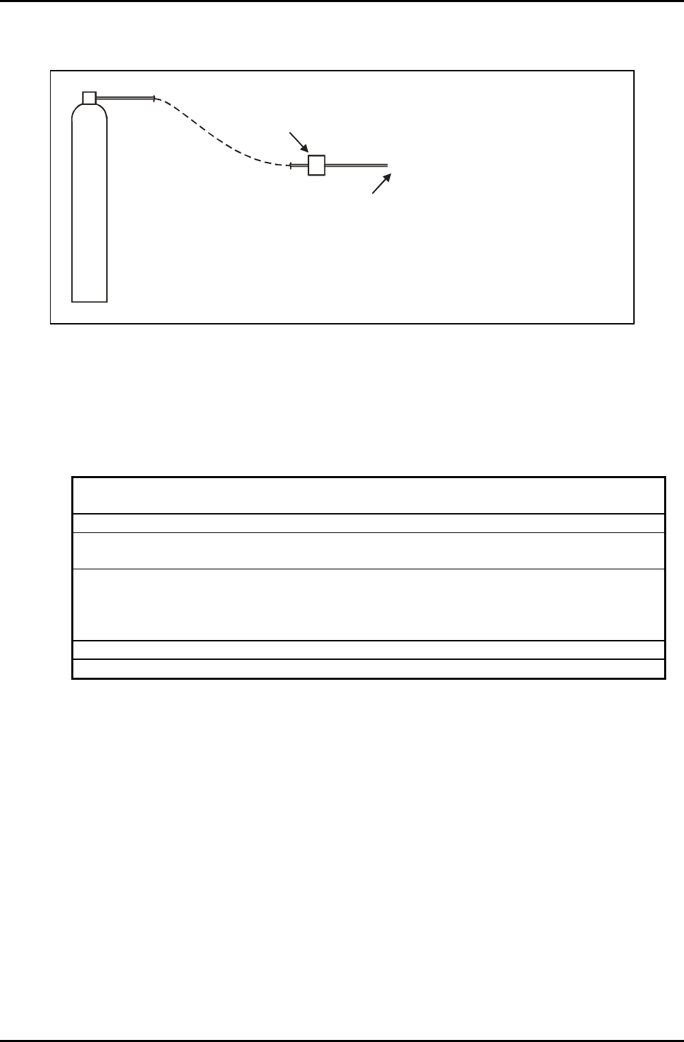
Fig 6.1: Recommended process gas supply installation
Semiconductor grade fittings and pressure regulators, together with electropolished stainless
steel tube must be used to ensure that gas quality is not degraded.
SKN= j~åÇ~íçêó=ëéÉÅáÑáÅ~íáçåë=Ñçê=éêçÅÉëë=Ö~ë=ëìééäáÉë=
• Pipework fittings and pressure
regulators:
Semiconductor grade
• Gas handling tubing: Electropolished stainless steel
• Purity: At least 99.99% or higher to satisfy
process requirements.
• Filtration: A 2-micron filter is fitted to each
gas line supplied as part of the
system. For other grades of filter,
please consult OIPT.
• Regulation: 0.5 to 5 bar (7.5 to 75 psig)
• Minimum pressure at input to system: 2 bar (30 psig)
SKNKN= póëíÉãë=ìëáåÖ=eÉäáìã=ï~ÑÉê=ÅççäáåÖ=
The specifications for the Helium gas supply are as for those of the process gases given in sub-
sections 6 and 6.1 with the exception that the maximum pressure at the inlet to the
pressure controller must not exceed 3.5 bar (43 psig). The design of the Helium
pressure controller is such that it can be destroyed by higher pressures.
Services Specifications
Issue 16: April 05 Page 14 of 22 Printed: 6-Jan-06, 8:44

System Manual lñÑçêÇ=fåëíêìãÉåíë=mä~ëã~=qÉÅÜåçäçÖó== lfmq=póëíÉãë
SKNKO= fåëí~ää~íáçå=çÑ=äçï=î~éçìê=éêÉëëìêÉ=Ö~ëÉë=EÉKÖK=pá`ä
Q
I=_`ä
P
I=`
Q
c
U
F=
The low vapour pressure can lead to condensation in the gas supply lines, particularly at cold
points or when the gas passes into a cooler region. This condensation can result in a build up
of liquid in the gas pipe, usually at the low points or u-bends in the gas line, often leading to
instability of gas flow, especially if liquid condenses or flows into the MFC.
The low vapour pressure can also result in very low gas pressure if the gas cylinder is very
cold, e.g. if it is kept outdoors in the winter.
Therefore, it is important to adhere to the following guidelines:
(A) It is necessary to keep the gas cylinder indoors (in an extracted gas cabinet) to avoid
loss of line pressure when the outside temperature is cold.
However, do
NOT heat the gas cylinder with a heated jacket as this can cause
condensation problems when the gas passes into the cooler gas lines. Room
temperature is warm enough to provide sufficient vapour pressure.
(B) It is important to maintain a positive temperature gradient from the cylinder to the
MFC, or at least keep them at the same temperature. The simplest method is to
position the gas cabinet close to the gas pod, minimising the chances of temperature
differences, reducing the length of the gas pipe, and hence minimising the chances
of condensation. If this is not possible, then it is necessary to heat the gas lines by
the use of heater tape.
The MFC will also need to be heated. OIPT offers a heated MFC kit for these gases.
Alternatively, heater tape can be wrapped around the MFC. However, in this case, it
may also be necessary to detach the MFC from the backing plate to avoid heat loss
through the plate, and to cover the MFC in insulation material to avoid cooling from
air flow within the gas pod (from the gas pod exhaust).
It will then be necessary to set the MFC temperature hotter than the gas line
temperature, which in turn is hotter than the gas cylinder temperature. A typical set-
up might be MFC 40 °C or above, gas line 30-40 °C, and gas cylinder at room
temperature.
(C) If condensation problems are suspected, it will be necessary to pump out the gas
lines completely, and optimise the heater tape arrangement and temperature
setpoints before refilling the gas line.
(D) For SiCl
4
it is important to use a dedicated SiCl
4
MFC as this is designed specifically for
low-pressure condensable SiCl
4
operation.
Services Specifications
Printed: 6-Jan-06, 8:44 Page 15 of 22 Issue 16: April 05

lfmq=póëíÉãë lñÑçêÇ=fåëíêìãÉåíë=mä~ëã~=qÉÅÜåçäçÖó== System Manual
TK= iáèìáÇ=káíêçÖÉå=
WARNING
IF LIQUID NITROGEN FACILITIES ARE NOT INSTALLED, OPERATED AND MAINTAINED
CORRECTLY, DANGEROUS SITUATIONS CAN RESULT. THESE INTRODUCE RISKS OF:
A) HAZARDOUS PRESSURE BUILD-UP CAUSED BY THE BOIL-OFF OF LIQUID
NITROGEN, WHICH CAN RESULT IN AN EXPLOSION.
B) PERSONAL INJURY FROM TOUCHING PIPEWORK OR OTHER SYSTEM
COMPONENTS CARRYING LIQUID NITROGEN. THIS RISK CAN REMAIN EVEN
AFTER VENTING THE CHAMBER.
C) ASPHYXIATION CAUSED BY THE BOILED-OFF LIQUID NITROGEN REPLACING
OXYGEN IN THE SYSTEM ENVIRONMENT.
TKN= j~åÇ~íçêó=oÉèìáêÉãÉåíë=Ñçê=iáèìáÇ=káíêçÖÉå=ëóëíÉãë=
• Ensure that the Liquid Nitrogen installation is carried out in accordance with
local safety regulations. This includes the following:
(a) No part of the Liquid Nitrogen circuit can become blocked with ice
or other contaminants.
(b) Adequate precautions, e.g. pressure relief valves, are fitted to
prevent hazardous pressure build-up from boil-off of the Liquid
Nitrogen.
(c) All system components carrying Liquid Nitrogen are adequately
insulated, and covered to prevent personnel touching exposed
components.
• Ensure that the installation is inspected by a Specialist to confirm that it is
safe to use. Inspections must be carried out before the system is
commissioned and at regular intervals throughout its life.
• Pipework from the Dewar to the system must be adequately insulated and
connected to the system via a
3
/
8
” Swagelok connector.
Services Specifications
Issue 16: April 05 Page 16 of 22 Printed: 6-Jan-06, 8:44