Utah-94-721002-System-Manual.pdf - 第245页
Equipment Manual lñÑçêÇ=fåëíêìãÉåíë=mä~ëã~=qÉÅÜåçäçÖó== mä~ëã~ä~Ä= f`m=NUM PK= aÉëÅêáéíáçå= PKN= cìåÅíáç å= The mä~ëã~ä~Ä f`mNUM is an Inductively Coupled Plasma (ICP) so urce suitable for the mä~ëã~ä~Ä = póëíÉã=NMM= or …

mä~ëã~ä~Ä=f`m=NUM lñÑçêÇ=fåëíêìãÉåíë=mä~ëã~=qÉÅÜåçäçÖó== Equipment Manual=
OK=pÉêîáÅÉë=
OKN= nì~äáí~íáîÉ=êÉèìáêÉãÉåíë=
The qualitative services requirements for the mä~ëã~ä~Ä
=
f`m=NUM source are given in Appendix S - ‘Services
Specifications for mä~ëã~ä~Ä=and=fçåÑ~Ä Systems’. This document gives generic information and
mandatory requirements for all services.
OKO= nì~åíáí~íáîÉ=êÉèìáêÉãÉåíë=
OKOKN= `ççäáåÖ=ï~íÉê=
The source has two cooling circuits:
¼ inch pipework circuit requiring 1 litre/minute
3
/
8
inch pipework circuit requiring 2 litres/minute
The
3
/
8
inch circuit can be put in series with the RF generator cooling provided the minimum flows of
both are satisfied.
Cooling water is required at a minimum flow rate of 2 litres/minute to the source. The RF generator
requires 4 litres/minute (1200W) or 8 litres/minute (3000W).
OKOKO= mêçÅÉëë=Ö~ë=
Process gas supplies are required for the source and for the process chamber. Types of gases and their
flow rates depend on the process application. Normally all gas is injected at the top of the source. A few
processes (especially PECVD processes) require some of the gas to be injected downstream.
OKOKP= oc=éçïÉê=
An RF generator is required to supply power to the automatch unit. The RF generator should have an
output impedance of 50 ohms and a minimum power rating of 1200W.
The maximum allowable RF power input to the automatch unit is 3kW.
OKOKQ= bäÉÅíêáÅ~ä=ëìééäó=
The electrical supply required for the automatch unit are is 24VDC at 2A maximum.
OKOKR= bñíê~Åíáçå=
The extraction collar fitted on the top cover must be connected to an extraction system having a
minimum flow rate of 1 m
3
/minute at 60 Pa extraction pressure.
This requirement can be waived for alumina tubes provided those responsible for machine safety
permit it. They should perform a risk assessment which considers breaking of the ICP tube during
processing.
The requirement cannot be waived for an ICP 180 fitted with a quartz tube, because UV emission from
the plasma will generate ozone.
ICP 180 Source
Issue 4: January 06 Page 4 of 26 Printed: 18-Jan-06, 8:44
Equipment Manual lñÑçêÇ=fåëíêìãÉåíë=mä~ëã~=qÉÅÜåçäçÖó== mä~ëã~ä~Ä=f`m=NUM
PK=aÉëÅêáéíáçå=
PKN= cìåÅíáçå=
The mä~ëã~ä~Ä f`mNUM is an Inductively Coupled Plasma (ICP) source suitable for the mä~ëã~ä~Ä
=
póëíÉã=NMM=or equivalent vacuum equipment. Its function is to create a highly ionized low pressure
plasma above a substrate, without the need to couple RF power to the plasma capacitively through the
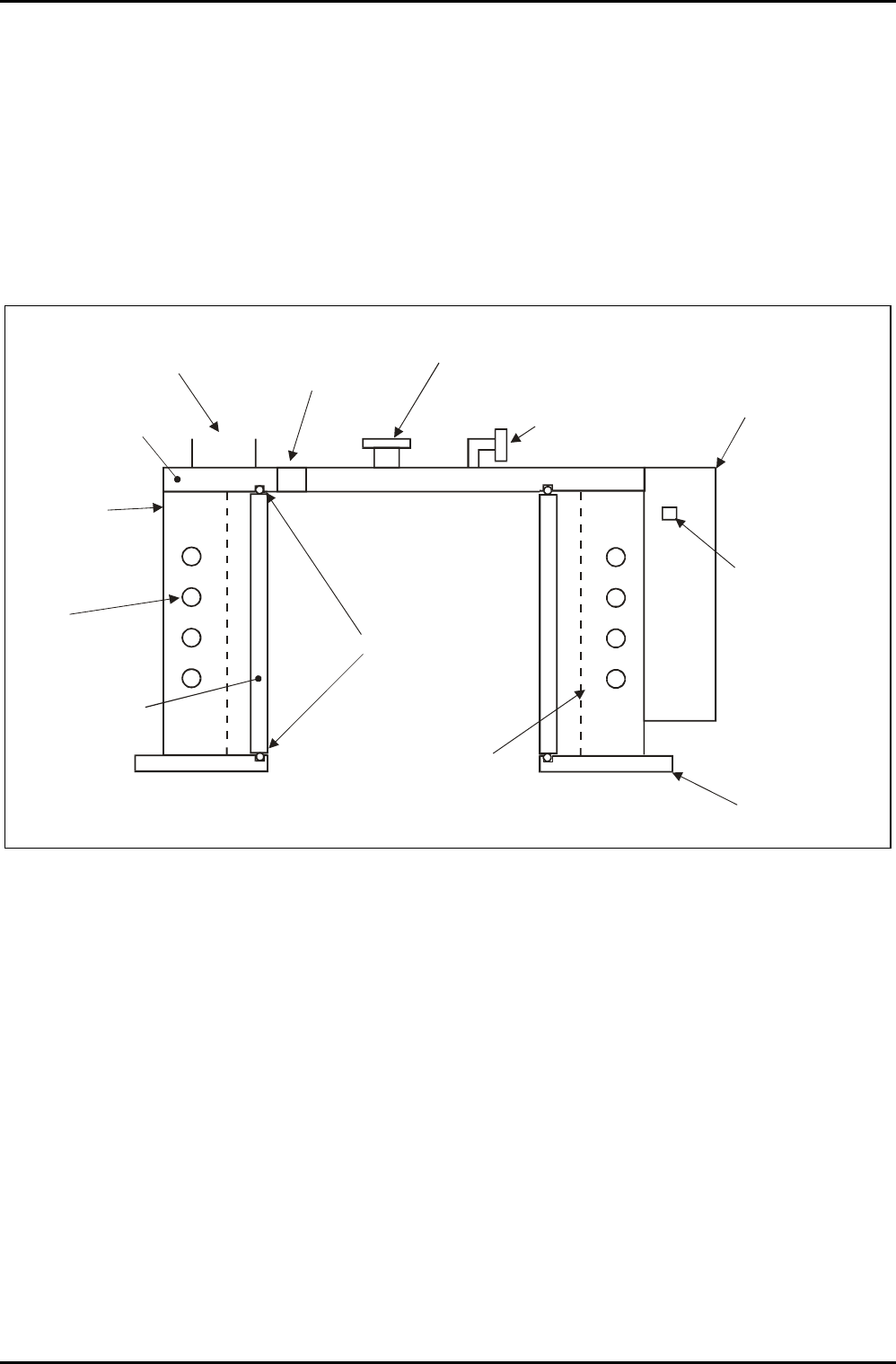
substrate. The principal components of the source are shown in Fig 1.
RF
INDUCTION
COIL
RF COIL
ENCLOSURE
ICP TOP
EXHAUST
SPIGOT
DIELECTRIC
TUBE
PLASMA
O RING
SEALS
PRESSURE
RELIEF PORT
BLANKED / VIEW
PORT
GAS INLET
RF MATCHING
UNIT
RF CONNECTION
CHAMBER LID
ELECTROSTATIC
SCREEN (OPTION)
Fig 1: ICP 180 source - cross section of principal components
Plasma is created by electromagnetic induction when an alternating high frequency current in the RF
induction coil causes a circulating current to flow in a low pressure plasma. The plasma can be initiated
by the induction coil or by power applied to another system electrode, usually RF power to the substrate
electrode.
To create a high circulating current in the RF coil in this non-resonant design without a high reflected
power, an RF tuning network with automatic matching is mounted close to the coil. RF power at
13.56MHz at up to 3kW is supplied via the coaxial N-type 50 ohm connector on the matching unit. The
matching unit contains motor-driven vacuum capacitors and a directional detection circuit, which acts to
make the load impedance presented to the RF generator as close as possible to 50 ohms.
The metal ICP top, RF coil enclosure, and chamber lid, together with the matching unit covers and vacuum
system underneath, form an enclosure to contain the strong electromagnetic radiation from the RF
components.
ICP 180 Source
Printed: 18-Jan-06, 8:44 Page 5 of 26 Issue 3 : December 00

mä~ëã~ä~Ä=f`m=NUM lñÑçêÇ=fåëíêìãÉåíë=mä~ëã~=qÉÅÜåçäçÖó== Equipment Manual=
WARNING
THE DIELECTRIC TUBE COULD FAIL CATASTROPHICALLY BY IMPLOSION WHEN
UNDER VACUUM. IF IT IS NECESSARY TO OPEN THE RF ENCLOSURE FOR ANY
REASON, VENT THE CHAMBER, OR WEAR APPROPRIATE PERSONAL PROTECTION.
WARNING
DO NOT OPERATE THE SOURCE WITHOUT THE COVERS PROPERLY ATTACHED. PARTS
OF THE CIRCUIT OPERATE AT LETHAL VOLTAGES. RADIATION BURNS MAY OCCUR TO
NEARBY PERSONNEL.
CAUTION
Nearby electrical equipment may experience RF interference if the source is
operated without all covers and lids forming the RF enclosure properly secured.
Other components of the ICP180 include:
• A gas inlet connection, ¼ inch VCR female nut, feeding gas to distribution holes in the ICP top
lid.
• A KF25 port, intended for laser interferometry.
• A 100mm diameter extraction collar.
WARNING
IF A QUARTZ ICP TUBE IS FITTED, ULTRA-VIOLET LIGHT FROM THE PLASMA CAN
FORM OZONE IN THE AIR INSIDE THE RF ENCLOSURE. EXTRACTION SHOULD BE
FITTED TO THIS PORT; EXTRACTION SHOULD BE FITTED IF THE GASES USED POSE A
HAZARD TO PERSONNEL SHOULD THE ICP TUBE BREAK.
• An electrostatic screen. This minimises capacitive coupling between the RF induction coil and the
plasma, which in turn reduces ion bombardment of the tube wall. It also eliminates cross-
coupling between the ICP RF supply and any other RF generator on the same chamber, making
phase-locking unnecessary. The electrostatic screen can be omitted if the ICP 180 is the only
plasma source on the chamber.
• A pressure relief port. Should the system become pressurised, this will automatically open to
prevent dangerous pressurisation of the ICP tube.
ICP 180 Source
Issue 4: January 06 Page 6 of 26 Printed: 18-Jan-06, 8:44